-
Open a product containing at least one junction with several branches.
-
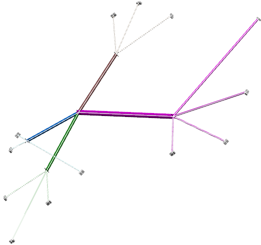
Generate the flattened view.
 The arrangement information of the segments is lost in the flattened document. - In this view, select the electrical geometry, and then create a drawing in the Drafting app.
-
From the
View Layout
section of the
action bar, click Front View.
The Generative view style dialog box appears
and the Generative view style option is selected by default. - From the flattened view, select a plane in the electrical geometry.
-
Click anywhere in the drawing to validate the
action.
The drawing view of the geometry, with junctions and segments, is generated.
-
From the
Electrical Dress-up
section of the
action bar, click Arrange Junction Section View
 . .
- In the drawing, hover over a junction to select it.
-
Click the 3D area to create the section view of the selected junction.
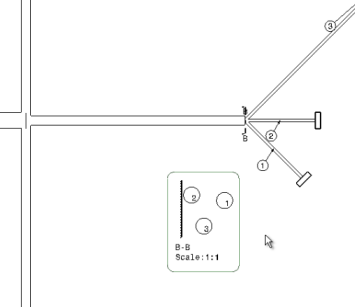
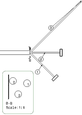
At the right bottom of the next image, you can see that a junction section view with balloon numbering is added in the drawing sheet. The same balloon numbering is attached to each corresponding cut segment with an arrow, allowing you to create a correlation between the segments of the flattened content present in the drawing and the segments in the junction section view. A node with the corresponding section view is added to the current sheet.  Find below a zoom and a description of the generated junction section view:

- A callout (B-B in the image) is created at the junction to show the viewing direction. The line of the callout is perpendicular to the fork axis, which is along the tangent of the branch curve at the fork extremity.
- A table reference line is created in the junction section view which is perpendicular to the fork axis. As explained at the beginning of the task, you need to mention a particular Chapter in Data Setup.
- The viewing direction is perpendicular to the plane in which the segment arrangement is done and from fork extremity towards the secondary segments of the fork.
- The axis system of the section view is the same as the constraint vector of the junction. Therefore, the orientation of the view is compatible with the torsion analysis. For more information, see Vectors.
|