Use an Auxiliary View
The auxiliary view enables you to generate a device section view which is perpendicular to the plane.
- Generate a 2D view of your flattened content.
- From the
View Layout
section of the
action bar, click Front View
 .
. - In your flattened content tab, select a reference plane.
The view is generated in the drawing. Note: For more information, see Drafting User's Guide: Creating Views: Creating a Front View.
 - From the
View Layout
section of the
action bar, click Front View
-
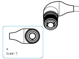
From the Electrical Dress-up section, click Device Section View
 .
. -
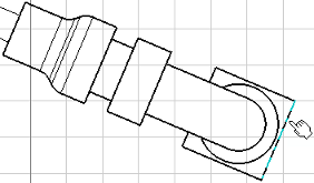
Select a device edge which is perpendicular to the view direction.
-
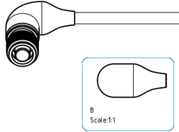
Click the sheet to generate the section view.
The section view is created perpendicular to the view direction of the device.Note: The view displays all the connectors linked to the selected device.

Tips: - You can move the position of the section view but only according to the direction of the callout (A arrow in our example).Note: To hide the callouts, clear the Create callout in active view option. For more information, see Native Apps Preferences Guide: Mechanical: 2D Layout for 3D Design: View Creation.
- A line representing the table reference can also be displayed. The symbol needs to be declared in your chapter in Data Setup using the following path:
intel_a\startup\Electrical\Drawing\Table_Reference.3dxml.
Important: If you edit the position of the assembly in Electrical Manufacturing Preparation, you can refresh the section view by clicking Update in Electrical Manufacturing Preparation, and then again in Drafting. By default, the alignment is not updated, so you need to edit the callout to recompute the alignment. For more information, see Drafting User's Guide: Customizing View Content: Modifying a Callout Geometry.
- You can move the position of the section view but only according to the direction of the callout (A arrow in our example).