You can
validate the junction arrangement of the flatten data
against the harness data. It helps to compare the flatten data and the harness data for their
relative compatibility and the compatibility with the manufacturing process.
Before you begin: Flatten the harness geometry using the Formboard command or open
the data flattened using Formboard command. If you open the flattened
data , synchronize it with its harness data.
From the Formboard section of the action bar, click Junction Validation.
The Junction Validation panel appears. By default, the
start and end points of the backbone are added as the start and the end points of the path
to analyze. The labels, START and END,
appear on a selected branch. The branch is colored in pink .
Note:
You can change the end point of the path to analyze.
In the Junction Validation panel, click
Finalize.
In the Junction Validation panel, the following
information is displayed:
The junctions in the selected path ordered from the start device to the end device
in the Junction column
The type of the junction between the following possible types in the
Junction Type column:
Junction with support
T-shape junction
Arranged junction
Non-arranged junction
The support instance name part for junctions with support in the
Support column. For other types of junctions,
NA is displayed.
The segment from which the junction is
analyzed in the selected path in the Primary Segment Path
column
The position of segments within the different junctions depending on their types is
displayed on the right side pane.
Commands to reframe and manipulate the segments.
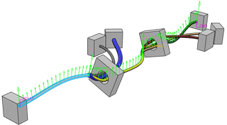
In the harness data, the selected path to analyze is displayed as below:
Big green vectors are displayed at the characteristic points such as devices,
supports, junction points, etc.
Smaller green vectors are displayed in between the big vectors. The green vector
indicates the orientation of the backbone and is normal to the flattened plane.
Note:
The pitch between two consecutive vectors is defined in the
Pitch box under Backbone Vector
Field, available at Me > Preferences > App Preferences > 3D Modeling > Electrical and Electronic Systems > Electrical Manufacturing Preparation > Electrical Manufacturing Preparation > Formboard.
Select the required junction.
The list of segments organized in the common support of the selected junction is
displayed below the table listing junctions. Based on the junction type, the panel
displays information as below:
Type of Junction
Columns Displayed
Junction with support
Secondary Segment Path: Displays name of the
segments defining the selected junction
Electrical Geometry: Name of electrical geometry
containing a segment
Diameter: Segment diameter value (mm)
Segment Position in Support: Segment position in
support in (U,V) axis system, V-axis being the filled vector at the entry of
the support and the origin is at the support center
Ambiguous: Ambiguity status of the segment (If the
segment profile crosses the ambiguity zone fully or partly, the segment
becomes ambiguous. This segment can be at any side of the backbone, left or
right.)
Ambiguity Offset: Ambiguity offset or width value
around the vector at the entry segment within which any segment is
ambiguous
You can specify the offset width as below:
In the Ambiguity zone width box under
Junction Ambiguity Zone, available at Me > Preferences > App Preferences > 3D Modeling > Electrical and Electronic Systems > Electrical Manufacturing Preparation > Electrical Manufacturing Preparation > Formboard
Network Weight: Network weight of the segment, in
other words the number of junctions from the segment end to the rest of its
network ends
If the segment profile is within the ambiguous zone, you can rotate (using
Rotate) segment
using the command available in the panel. Segment Profile in Ambiguous Zone Segment Profile Not in Ambiguous Zone
T-shape junction
Secondary Segment Path: Displays name of the
segments defining the selected junction
Electrical Geometry: Name of electrical geometry
containing a segment
Diameter: Segment diameter value (mm)
Angle with MFA vector : Angle between the segment
tangent at the junction point with the field vector at the junction
point
Ambiguous: Ambiguity status of the segment
If
the segment center curve is within the ambiguity zone defined by a conic
zone around the field vector, it is considered as ambiguous.
Ambiguity Angle: The ambiguity zone angle is
defined in the Ambiguity zone identification angle
box under T-Shape Junction, available at Me > Preferences > App Preferences > 3D Modeling > Electrical and Electronic Systems > Electrical Manufacturing Preparation > Electrical Manufacturing Preparation > Formboard
Network Weight: Network weight of the segment, in
other words the number of junctions from the segment end to the rest of its
network ends
If the segment center curve is within the ambiguous zone, you can mirror
(using Mirror)the
segment using the command available in the panel. The segment is represented by
a square with the segment color and diameter value as width. Segment Center Curve in Ambiguous Zone
In the harness data, the selected junction is highlighted.
Under Harness, click Reframe to reframe
the selected junction in the harness data.
You can also click Center Tree to highlight the node of the
primary segment of the junction in the tree when no segment is selected in the segment
list.
Note:
If you click the commands under Flatten, the selected
junction is reframed in the flattened data or its node is highlighted in the tree.
After doing the required manipulations, click Close or the
Junction Validation on the action bar to close the operation.
 .
The Junction Validation panel appears. By default, the start and end points of the backbone are added as the start and the end points of the path to analyze. The labels, START and END, appear on a selected branch. The branch is colored in pink
.
The Junction Validation panel appears. By default, the start and end points of the backbone are added as the start and the end points of the path to analyze. The labels, START and END, appear on a selected branch. The branch is colored in pink .
Note: You can change the end point of the path to analyze.
.
Note: You can change the end point of the path to analyze. > Preferences > App Preferences > 3D Modeling
.
> Preferences > App Preferences > 3D Modeling
. ) segment
using the command available in the panel.
) segment
using the command available in the panel. 

 )the
segment using the command available in the panel. The segment is represented by
a square with the segment color and diameter value as width.
)the
segment using the command available in the panel. The segment is represented by
a square with the segment color and diameter value as width. 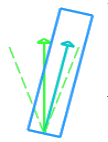
 on the action bar to close the operation.