You can instantiate tables of required
dimensions declared in Data Setup.
Before you begin: Create the valid table of required dimensions and declare it as a resource in Data Setup. For more information about valid tables, see Available Resources.
From the Formboard section of the action bar, click Table Management.
In the Table Management panel, from the
Table list, select the required table to instantiate.
If the table is valid, under Dimenstions, the
length and the width of the table are displayed.
Double-click in the work area.
The table is instantiated and placed at an offset of 150 mm to the
left of the start point of the flatten data.
The table is placed along x-axis on X-Y plane at an offset distance
value specified. For more information about
specifying offset distance, see Generate Layout.
The node with the product name with
(Tooling.1) as a suffix, is added to the
tree under flatten product. Under this node, nodes are added that
displays the table names of instantiated tables.
Notes:
If the flatten data is present in the root product, the first table
is placed at the starting device of the flatten data.
If the flatten data is not present in the root product, the first
table is placed at global origin.
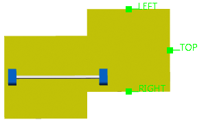
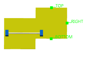
If you hover over the first instantiated table,
three labels (Top,
Right, and Bottom)
representing the axis system appear. The label,
Left, is unavailable as the first table
is always placed at the extreme left of the data.
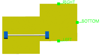
To instantiate another table, select the required table from the
Table list and select the required label to position
the table with reference to first table.
An engineering connection is created between corresponding axis system
and the table is positioned.
For example, if you select the
Right label, an engineering connection is
created between axis system represented by the
Right label of the source table and
opposite axis system, Left of the target
table which is going to be instantiated.
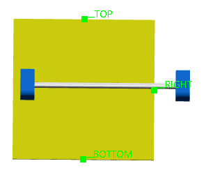
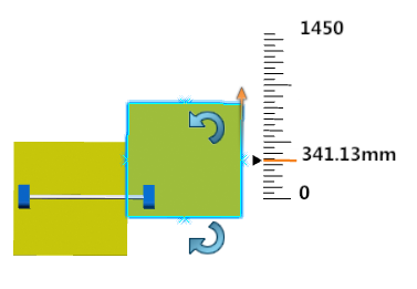
A ruler appears to manipulate the table along the axis system selected
to instantiate the table.
Arrows appear on adjacent axis system to rotate the table. For example,
if you select the RIGHT label of the source
table, the arrows are placed on the axis system represented by
TOP and BOTTOM labels.
Table Instantiated Selecting the Right Label
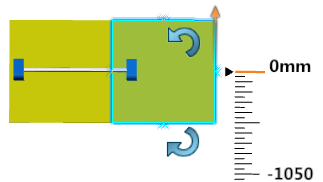
Manipulate the table along the axis system selected to instantiate the table.
Manipulation of Along y-axis of the Selected Axis
System
Resulting Table after Manipulation
Rotate the table in required direction. To do so:
Click to
rotate the axis system and labels representing them in a clockwise
direction.
Click to rotate the axis
system and labels representing them in a counterclockwise direction.
Clockwise Rotation
Counterclockwise Rotation
Close the panel to end the command.
You can check the engineering connections under table name
node, created during table instantiation.
 .
.
 to
rotate the axis system and labels representing them in a clockwise
direction.
to
rotate the axis system and labels representing them in a clockwise
direction.  to rotate the axis
system and labels representing them in a counterclockwise direction.
to rotate the axis
system and labels representing them in a counterclockwise direction.