Display Pins on a Harness Connector
-
From the tree, right-click the harness connector and select
Place in View.
The symbol appears and follows your pointer in the diagram view.
-
Click the diagram view at the convenient place to insert the symbol.
The symbol is placed and a context toolbar appears.
-
On the context toolbar,
select Display Connector and Pins
 . .
-
In the Manage Connector and Pins Display dialog box, select the Display Connector Port
check box to display the connector port.
-
In the Step box, type the step value to define the distance between two pins.
-
In the Offset box, type the offset value to define distance between the top of the connector and the first pin.
Note:
The unit for the step and the offset values is the millimeter.
- Optional: To change the position of a pin, drag it to the desired position.
- Select the boxes of the pins to be displayed.
Note:
A pin cannot be selected if the Lock pin multiple representation option is selected in
and if the pin is already represented in a diagram view loaded in session. .
- Click OK.
The connector representation with the selected pins is placed in the diagram view. The pins are placed on the right side of the connector and the connector port on the left side. 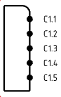 - To change the position of a pin when placed in the diagram view, drag it to the desired position.
Note:
If you press shift while dragging a pin, the pin which was previously at the selected position is positioned just under the moved pin. All the pins below are shifted down.
The moved pin is placed at the selected position. The pin which was previously at this position takes the position of the pin which has been moved.
Display Pins on a Disconnect
-
From the tree, right-click the disconnect and select
Place in View.
The symbol appears and follows your pointer in the diagram view.
-
To insert the symbol, click the diagram view at the convenient place.
The symbol is placed and a context toolbar appears.
-
In the Step box, type the step value to define the distance between two pins.
- From the context toolbar, select Display Connector and Pins .
-
In the Offset box, enter the offset value to define distance between the top of the connector and the first pin.
Note:
The unit for the step and the offset values is the millimeter.
- Select one of the following options under Style:
- Both: to display the whole disconnect symbol with the plug and the receptacle
- Receptacle: to display only the receptacle
- Plug: to display only the plug
- Select the boxes of the pins to be displayed.
Note:
A pin cannot be selected if the Lock pins multiple representation option is selected in
and if the pin is already represented in a diagram view loaded in session. .
- Click OK.
The connector representation with the selected pins is placed in the diagram view. The pins of the receptacle and the plug are placed respectively on the left side and on the right side of the disconnect.  - To change the position of a pin when placed in the diagram view, drag it to the desired position.
Note:
If you press shift while dragging a pin, the pin which was previously at the selected position is positioned just under the moved pin. All the pins below are shifted down.
The moved pin is placed at the selected position. The pin which was previously at this position takes the position of the pin which has been moved.
|


 > Preferences > App Preferences > 3D Modeling
and if the pin is already represented in a diagram view loaded in session. .
> Preferences > App Preferences > 3D Modeling
and if the pin is already represented in a diagram view loaded in session. .