-
Create a disconnect containing three pins.
Note:
When creating a disconnect, two connector ports are created. Each port has a Style attribute in its properties identifying it as plug or receptacle.
-
Double-click the diagram view.
-
In the tree, under Disconnect > Ports,
right-click the plug port and select Place in View.
The symbol associated with the plug part appears and follows your pointer. -
Click the diagram view to
place the plug symbol.
-
On the context toolbar,
click Display Connector and Pins
 . .
-
In the Manage Connector and Pins Display dialog box, select the
pins to displayed.
- Click the plug symbol and click Smart Positioning Harness Connector
 on the context toolbar. on the context toolbar. The plug and receptacle symbols are connected. The pins of the receptacle are aligned with the pins of the plug, in the same order. 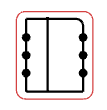
|


