About Cable Route Representation

This section describes available resources to customize the display of cable routes.

This page discusses:

Cable Type Definition

You can represent Different cable types such as twisted or shielded cables.

Cable Ends Representation

You can define a symbol to insert on each end of the cable.

In the Electrical Logical resources resource of the Data Setup app, a logical reference representing the cable ends should be assigned to the Default Cable Ends Representation resource.

Symbol Size Definition

You can customize the size of your symbol.

In the Electrical Logical resources resource of Data Setup, an .xls sheet should be assigned to the Cable Ends Properties resource.

The .xls sheet must be completed as follows:

  • First column: distance between the component symbol and the cable's end symbol (d1).
  • Second column: distance between the last wire of the cable and the top/bottom of the cable end's symbol (d2).

Symbol Size and Position Management

Moving a Connector

The position of the cable end’s representation is modified accordingly if you perform one of the following manipulations on the connector's symbol:

  • Translation
  • Rotation
  • Flip
    Note: Cable end’s representations are not flipped when the connector is flipped.
  • Resize/scale

The distance between the connector's symbol and the cable end’s representation is kept. The top and bottom (d2) are also kept.

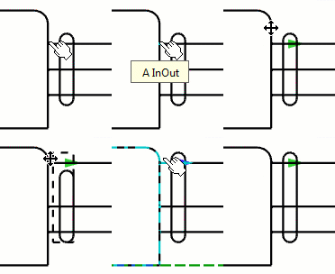
While moving the connector, a ghost symbol appears in a dotted line, showing the future size and position of the cable end’s representation.

Moving a Pin

Moving a pin linked to the first or last wire of the cable increases or decreases the size of the cable end representation.

The cable end representation also increases or decreases when:

  • Moving pin over the highest lowest pin.
  • Swapping two pins.

Moving Cable End’s Representation

The cable end’s representation can only move along the first segment of the routes. The top and bottom (d2) are also kept.

The new distance between the connector and the cable end’s representation is kept.

Cables Routes Display

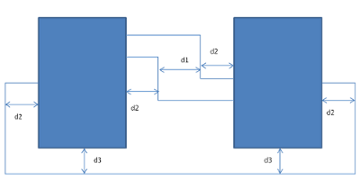
You can define the distance between the multiple wires of the cable to make the electrical model easier to understand in the diagram view.

In the Electrical Logical resources resource of the Data Setup app, an .xls sheet should be assigned to the Route Spacing Parameters resource.

The .xls sheet must be completed as follows:

  • First column: distance between the segments (d1)
  • Second column: distance between the port and the segment (d2)
  • Third column: minimum distance between the component and the segment (d3).