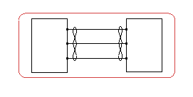
- In the tree, right-click the cable reference and select Route in View.
- In the Route Cable Options dialog box, define the minimum distance between wires in the Wire distance box.
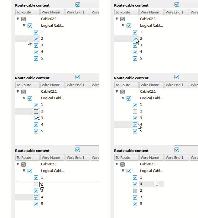
- Choose and organize the elements to be routed:
- In the To Route column, clear the elements not to be routed.
Note:
To route only the cable, clear the Route cable content option.
- To order the content to be routed, drag the elements to the desired location.
- In the Port selection option box, choose the way the ports are selected:
| Option | Description |
|---|
 | The ports are selected in the clockwise direction. |
|---|
 | The ports are selected in the counterclockwise direction. |
|---|
 | The ports are selected manually. |
|---|
- According to the selection mode, do one of the following actions:
Note:
Once you have selected the first pin, you can no longer change the mode of selection.
 and
and  : Click the first pin then the second pin of the first wire.
 :
: - On the first component, click all the pins to be connected.
- On the second component, click all the pins to be connected.
All the selected wires of the cable are routed. Note that in this scenario, a symbol representation of the cable ends is inserted. You can display the symbol representation even if the cable is not fully routed by selecting the Allows partial cable end placement option in
, select Cable content option. For more information, see Native Apps Preferences
Guide: Schematic.


