-
From the Edition section of the action bar,
click Create New Reference
 .
.
The New content dialog box appears.
- In the New content dialog box, expand the Electrical Logical tab and
right-click Logical Cable.
-
Select the Set attributes at creation option.
Note:
This option remains selected when creating another cable.
-
Click Logical Cable.
The Logical Cable dialog box appears.
-
Type a name for your cable reference.
-
In the Number of Groups box, enter the required number of cables
to be created. These cables are contained in the parent cable (Cable
1).
-
In the Number of Conductors by Group box, enter the required
number of wires to be created for each cable.
- If you want to identify the wires according to:
- In the Groups Type list, select a type for cables created under the parent cable.
Note:
This option can only be defined when there is at least one cable created under the parent cable (Cable 1).
A representation of the cable ends with a type matching the attribute of the Groups Type box is retrieved from Data Setup, when defined.
-
Click OK when done.
The Route Cable Content dialog box appears
- In the Wire distance box, define the minimum distance between wires.
- In the Port selection option box, choose the way the ports are selected:
| Option | Description |
|---|
 | the port selection is done in a clockwise direction. |
|---|
 | the port selection is done in a counterclockwise direction. |
|---|
 | the port selection is done manually. |
|---|
- According to the selection mode, do one of the following actions:
Note:
Once you have selected the first pin, you can no longer change the mode of
selection.
- and : click the first pin then the second pin of the first wire.
- :
- On the first component, click all the pins to be connected.
- On the second component, click all the pins to be connected.
-
Click the first component.
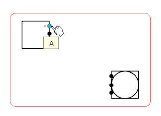
A context toolbar appears, containing commands to create an elbow or a straight route line.
-
Click at a convenient place to insert the first set of on-sheet connectors.
A
context toolbar appears, containing the command to create the on-sheet connectors.

-
Click Sheet Connector.
The first on-sheet connectors are created.

- In the tree, right-click the cable reference and select Route in View .
The Route Command dialog box appears.
- Select the second component.
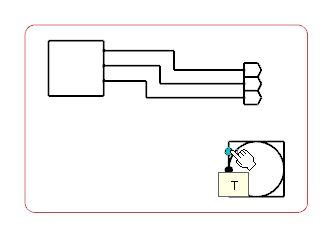
A context toolbar appears, containing commands to create an elbow or a straight route line.
- Click at a convenient place to insert the second set of on-sheet connectors.
A
context toolbar appears, containing the command to create the on-sheet connectors.
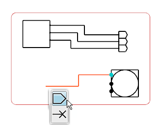
- Select Sheet Connector.
The on-sheet connectors are created for the second components.
Note:
To delete the sheet connector, right-click the sheet connector symbol and select Delete. The sheet symbol and the route connected to it are removed from the diagram view.
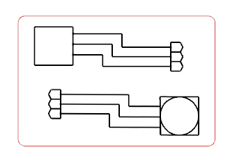
The content of the cable has been routed with on-sheet connectors.
