-
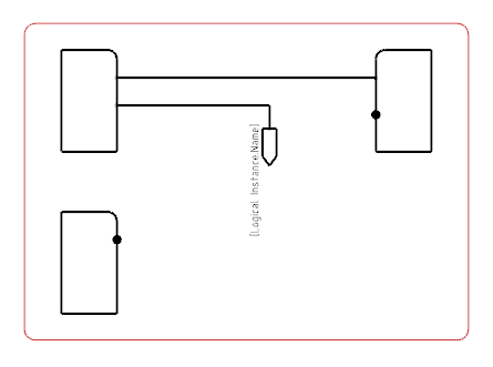
Create a logical reference and insert a symbol representation under the reference.
-
Double-click the symbol object to edit the symbol representation in Symbol Design.
-
Create an on-sheet or an off-sheet symbol.
-
Create a text template. For more information about the creation of text templates, see
Creating Texts.
Note:
If no connection point exists within the symbol, a connection point is automatically
created at the origin ordinate of the on-sheet symbol.
-
In the Link Template
dialog box, define a link template:
-
In the Package box, select Electrical Logical.
-
In the Type box, select Logical Single Connector.
- In the PLMEntity box, select Title.
- Click Insert.
-
In Data Setup, create a new resource set in Diagram Resources.
-
Assign the logical reference to the On Sheet Symbol for Same Sheet Context resource.
- Optional: Define the following criteria:
- Routable Type: Associates a type of route line to your sheet connector representation.
- Default: Defines the representation as the default one.
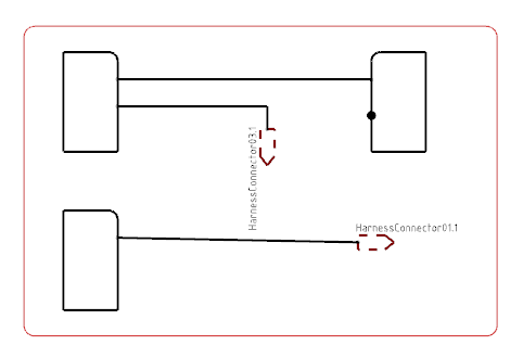
- In the diagram view, route the first part of your wire with an on-sheet connector.

Note:
The first symbol to be inserted is always the off-sheet symbol. If the second symbol is placed on the same sheet, the symbol of the first sheet connector is updated with the on-sheet symbol.
- Route the second part of your wire with an on sheet connector.

The text applied to the symbols appears in the diagram view. The first on-sheet symbol displays the title of the target logical harness connector. The second on-sheet symbol displays the title of the source logical harness connector.
|