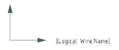
-
Create a logical reference and insert a symbol representation under the reference.
-
To edit the symbol representation in Symbol Design, double-click the symbol object.
-
Create a text template. For more information about the creation of text templates, see Drafting User's Guide: Managing Text and Table Templates: Working with Text and Table Templates.

-
In the Link Template
dialog box, define a link template:
-
In the Package box, select Electrical Logical.
-
In the Type box, select Logical Wire.
- In the PLMEntity box, select Title.
- Click Insert.
- From the Tools section of the action bar, click Object Properties.
The Object Properties panel appears. - Click Text and select
 to define the anchor point of the text. to define the anchor point of the text.Note:
For more information about anchor points, see Drafting User's Guide > Managing Text and
Table Templates > Working with Text and Table Templates.
- Save.
-
In Data Setup, create a new resource set in Electrical Logical Resource.
-
Assign the logical reference to the Default Text on Electrical Conductors resource and set the following parameters:
- Click OK when done.
The resource set is added under Electrical logical resources. - Associate your resource set with a project.
- Click Close.
A message appears asking you if you want to save. - Click Yes to save.
- In the diagram view, create and route a wire.
The text template is replaced by the name of the wire and is inserted in the diagram view.  Note:
If the Middle of Route option is selected and you modify the length of the route, the text does not reposition itself at the center of the route.
|

 to define the anchor point of the text.Note: For more information about anchor points, see Drafting User's Guide > Managing Text and Table Templates > Working with Text and Table Templates.
 Note: If the Middle of Route option is selected and you modify the length of the route, the text does not reposition itself at the center of the route.