Inserting a Component on a Route

You can insert a component on a route or at the end of a route.

Warning: The component cannot be inserted on the route if the ports directions are not compatible.

This task shows you how to:

Insert a Symbol on a Route

You can insert a symbol on a route.

Important: The inserted component must be a splice or a disconnect.

Before you begin: Open an existing diagram view containing:
  • A logical reference under the Logical node
  • A disconnect with symbol representation
  • A route between two symbols
  1. In the tree, right-click the logical reference and select Insert Existing Logical Component.
    The Select an existing logical component dialog box appears.
  2. In the tree, select the disconnect reference.

    Important: You can select a disconnect or a splice reference from a catalog, from existing, or from session.

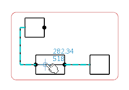
  3. Move the symbol over the route.

    A colored-dashed line is displayed showing the new routes. The pointer changes into a hand when a wire is selected:

  4. Click the route to insert the symbol.
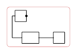
    The symbol is inserted.

    Note: The initial route is redesigned according to the inserted symbol. Simultaneously, an instance of the initial wire is routed between the two other pins.

Insert a Symbol on an Unconnected Route End

You can insert a symbol at the end of an unconnected electrical route line.

Before you begin: Open an existing diagram view containing:
  • A logical reference under the Logical node
  • A symbol connected to a route
  • A symbol to be connected
  1. In the tree, right-click the component to be inserted, and select Place in View.

    Tip: You can select a component from a catalog or in session.

    The symbol appears and follows your pointer.
  2. Move the symbol over the end of the electrical route line.

    The electrical route line is highlighted.
  3. Click the route end to insert the component.

    The symbol is connected at the end of the unconnected electrical route line.

Insert a Symbol on a Connected Route End

You can insert a symbol at the end of a connected electrical route line. The newly inserted symbol is connected to the other symbol and to the electrical route line.

Before you begin: Open an existing diagram view containing:
  • A logical reference under the Logical node
  • A symbol connected to a route
  • A symbol to be connected
  1. In the tree, right-click the component to be inserted, and select Place in View from the context menu.

    Tip: You can select a component from a catalog or in session.

    The symbol appears and follows your pointer.
  2. Move the symbol over the connected end of the electrical route line.

    The electrical route line and the connection point, which connects the two components are highlighted.
  3. Click the route end to insert the symbol.

    The symbol is connected at the end of the connected electrical route line.