About Net to Wire Data Generation

This topic describes the different levels of definition that are used for the generation of the wiring data.

This page discusses:

Levels of Definition

The net to wires process comprises four levels of definition:

  • The system (agnostic) architecture
  • The electrical architecture (EEW)
  • The electrical net definition
  • The electrical wiring definition

The following links between the objects of the different steps must be created to retrieve the following objects:

  • The corresponding component volume node from a logical equipment of the system architecture
  • The corresponding interface volume node from a logical Terminal Block container defined in the wiring definition
  • The corresponding derivation volume from a logical Terminal Block of the wiring definition
  • The implemented EEW Logical Signal from the net group of the net definition
  • The implemented logical system architecture Signal from the EEW Logical Signal
  • The implemented EEW equipment from equipment of the net definition
  • The implemented logical architecture Equipment from the EEW equipment

This equivalent routing is, for each net group of a net, the routing of the corresponding product link of the agnostic architecture in the 3D mockup:
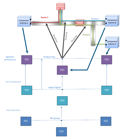
3D Mockup

The 3D simplified mockup is used to reserve space for the equipment components and their connections.

Each product of the 3D mockup is a volume. It can be a component volume, a derivation volume, or an interface volume. For more information, see Systems Space Reservation: Working with Volumes: About Volumes.

A component volume contains equipment components. It has a specific description, EE or RE, respectively emitter equipment or receiver equipment. They are represented in green for emitter equipment components, and blue for receiver equipment components.

A derivation volume contains logical derivation. Its description is DV.

An interface volume contains logical cuts. Its description is IV.


The product link showed above is routed in the 3D mockup.

The resulting route is a graph containing:

  • Nodes: Component volumes, derivation volumes, and interface volumes
  • Edges: Connects two nodes


Each node has a type: component volume, derivation volume, and interface node. For each interface node, the aggregating interface volume must be identified.

Wiring Data Generation

The wiring definition is computed based on the 3D mockup and net definition.

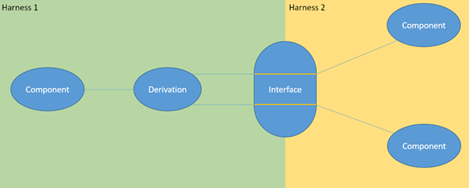
The following example illustrates what is generated according to the input graph.

The wiring definition process includes the following steps:

  • Creating the logical cuts, logical derivation, and logical wires
  • Grouping the logical wires under logical cables
  • Assigning the correct connector to each equipment

Cable Properties

Cable Type

The cable type depends on the net group. The Cable Family attribute of the net group reference is used in an Engineering Specification Capture & Reuse basic table to determine the cable type.

The table must be defined as follows:

  • A Cable Code column referencing all the possible tags.
  • A Cable Type column referencing the corresponding logical cable type.

The value in the Criteria attribute must be CableTypeTable.

Cable and Content Name

You can implement a business rule to define a specific name for the cable and its wires. For more information, see Defining The Name For a Cable and its Content (ELE_CustomiseCableNames).

Gauge Computation

The gauge, diameter, section, and linear mass of the cables are computed using the maximum nominal current used by the equipment pins. The maximal nominal current is used in an Engineering Specification Capture & Reuse basic table to identify the right gauge for this current. The value in the Techno table description must be the material of the table.

The table must be defined as follows:

Every column of the table must have the right format.

The value in the Criteria attribute must be NominalCurrentTable.

There is one table per material. The material is retrieved from the Cable Type table.

Node Content and Connection

For each node end, a component is created to connect the wires of the cable.

Component Node

For a component node, the harness connector connected to the equipment connector is created or reused.

If it does not exist:

  1. The compatibility table in Engineering Specification Capture & Reuse is used to select the right connector.
  2. If no compatible connector is found, a new reference with the same number of ports is created and connected to the equipment port.

Connection

The wires are connected to the right pin. For example, a wire allocated to the net1 net is connected to the pin that has the net1 signal.

Derivation Node

Derivation nodes are used to connect cables.

Each derivation node location is identified through its container. If no container is found for the derivation, a derivation container is created.

All the cables are allocated to the same net group, have the same number of wires, and each wire is allocated to the same set of nets.

For each net in the net group, a logical terminal board with only one terminal is created. The terminal has the same number of pins as the number of edges of the node.

All the terminal boards are allocated to the derivation container.

Connection

All the wires connected to the net are connected to a pin.

Interface Node

Interface nodes are used to split a cable line with connectors.

During the wiring generation process, each connector is created in the harness edge, and is allocated to the interface container corresponding to the node.

Connection

For each edge, the corresponding cable is connected to its connector. It connects the wire to the pins.

The corresponding connectors are connected two by two to connect the two cables.

At the end of the process, the wires of the same net are connected to pins in the same order.