Placing Relay Content in a Electrotechnical Diagrams

You can place the contacts and the operating devices of a relay in a diagram view. Once the relay content is placed, you can generate the contacts grid.


Before you begin:
  • In Me > Preferences > App Preferences > 3D Modeling > Systems Architecture > Electrical Sys. Design > Relay Representation, select the IE Representation option in the Relay Type area. For more information, see Native Apps Preferences Guide: Relay Representation.
  • Under a relay, add three contacts and an operating device using the Manage Relay Content command.
  • Create a diagram view.
  1. Double-click the diagram view.
  2. Right-click the contact and select Place in View.
  3. Click in the diagram view to place the contact.
  4. Repeat Steps 2 and 3 to place the other contacts.
  5. In the tree, right-click the operating device and select Place in View.
  6. Click in the diagram view to place the operating device.
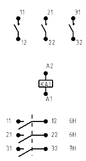
  7. Right-click the root of the system and select Create Contact Grid.

    Note: In this scenario, a frame has been inserted and text templates have been defined on the contact symbol to display the frame coordinates of the contacts.

    In the diagram view, the contacts grid is created below the operating device. It represents the content of the relay.