Managing Connections via the Spreadsheet

You can use the Spreadsheet to display, edit and create logical connections between electrical components.

This task shows you how to:

Display Electrical Connections

You can display and edit electrical connections directly in the Spreadsheet table, via the Display Additional Properties command. You can display or create single-value connections. The following scenario shows you how to connect the origin (From) and the ends (To) of a wire.

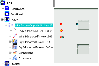
  1. Create a logical component with a wire and two equipments containing two pins.


  2. Click Spreadsheet from the Edition section of the action bar.
    The Spreadsheet opens, and displays the content of the active component.

Create Logical Connections Between Connector Ports

You can create a logical connection between two connector ports using the Connected Component attribute. This attribute can be read, edited, exported or imported via the Spread Sheet Editor.

Before you begin:
  • A logical equipment and a logical harness connector are created under a logical reference.
  • A connector port is created under the equipement and the harness connector.
  1. In the Spreadsheet Editor, click the Connected Component cell of the equipment's connector port.
  2. Click the port of the harness connector.
    A connection is created between the two connector ports.
    Note: To delete the connection, select one of the Connected Component attribute, pressi Suppr, and then Enter to validate (or click the background).

    When exporting the Spreadsheet table, the Connected Component attribute is exported has an occurrence. For more information about the export, see Exporting a Spreadsheet

    During spreadsheet file is imported, a logical connection is created if the Connected Component attribute is specified and if the connection between those two elements does not exist.

Create Single-value Connections

You can create electrical connections directly in the Spreadsheet table, via the Display Additional Properties command.

  1. Click Display/Hide Additional Properties .
    The Additional Properties dialog box appears and displays more information about the selected objects.
    Note: As there is no connection between the wire and the equipments, the From and To cells are empty.
  2. Place your pointer in the From empty cell.
    The color of the From cell changes indicating we have switched in the edition mode:

  3. Select pin 1 of the Equipment 1 in the Spreadsheet or in the tree.
    The name of the selected element appears in the Additional Properties window. A connection now exists between the wire and Equipment 1:

  4. In the Additional Properties window, click the empty cell To and select pin B in Equipment 2.
    The cell contains the path and name of pin B and a connection is created between the wire and Equipment 2:

    Notes:
    • You can change the connection by clicking the From or To cell and selecting another pin in the Spreadsheet or in the tree.
    • You can delete this connection by clicking the From or To cell, pressing the Suppr key and Enter to validate (or click the background).

Create Multiple-value Connections

You can display or create multiple-value connections, for example: the implement links of a net.

Before you begin:
  • Open an app containing an existing connection between a net and the pin (Pin A) of an equipment (Equipment 2).
  • Create a logical component with a net and two equipments containing two pins.
  1. Click Display/Hide Additional Properties .
    The Additional Properties dialog box appears and displays more information about the selected objects.
  2. Select the Net Ends cell.
    Another box appears with the existing connection. You can add/remove pins or ports in this window.


  3. Click and select Pin B of the Equipment 3.


  4. Click the background to validate.
    When there is more than one connection, the Net Ends cell contains the Multiple attribute. Otherwise when there is only one connection, you can read the name of the pin or port in this cell. If you move the pointer over the Net Ends cell, you can see the name and path of the pins or ports:

  5. Close the Additional Properties dialog box and you can visualize the new connections:


    Warning: If you add connections and click Cancel , the last modifications will not be taken into account. To validate the last connections, you need to click the background.
  6. To remove a value in Net Ends, click Multiple, select a pin or port reference and click . Click the background to validate this removal.