Customizing Measurements | |||||
|
| ||||
-
Select the measurement.

-
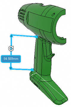
To position the measurement, drag its label, its extension lines, or its
dimension line.
Important: For the following cases, the selected elements define the direction of the extension lines and you cannot change this direction: - If you are measuring the distance between two parallel axes, the extension lines are aligned to the axes of the selected elements.
- If you are measuring the distance between two nonparallel axes or finite lines, the extension lines' direction is defined by the first selected element.
- If you are measuring the distance between two elements and the
dimension line is perpendicular to a normal to the selected element
or the selected lines or axes, the direction of the extension line
is defined by a normal and the viewing direction.
For different geometries, the following normals are considered:
- For a point on a surface, normal to the surface at the selected point is considered.
- For an arc or circle's center point, the normal to the plane of the arc/circle at the center point is considered.
-
For an arc or circle, the normal to the plane defined on the arc/circle at the point from where the minimum distance is found, is considered.
- In the above case if the extensions lines are close to the viewing direction, the extension lines are perpendicular to the axes or the normal.
- If you are measuring the distance between two parallel planes and if the dimension line is orthogonal to both the planes, the direction of the extension lines is defined by the dimension line and the viewing direction.
-
Choose from the options available in the context toolbar.
Option Description 
Switches between the radius display and diameter display. The selection is saved for the future measurements.

Applies the selected style to measurement. You can select one of the following styles:
-
 : Default
 -
 : Light
 -
 : Measure
 -
 : Note
 -
 : Validate
 -
 : Warning
 -
 : Danger

Increases the font size in the label.

Decreases the font size in the label.

Lets you customize the graphical properties. This option is only available after the measure is created. -
-
Right-click the measurement and select the following options:
- Leader End Type: Select one of the leader end types.
- Point Type: Select one of the point types. These options changes the appearance of the point that is being measured.
- Extremity Type: Select one of the extremity types.
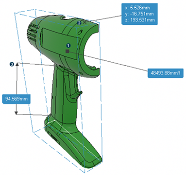
The following image shows the examples of leader end, point, and extremity:

Where,
Icon Type 1 Leader end 2 Point 3 Extremity These options are available depending on the type of measurement.
-
Right-click the measurement and select Properties
 .
The Properties dialog box is displayed.You can customize the appearance of the measurement result representation using the following options:
.
The Properties dialog box is displayed.You can customize the appearance of the measurement result representation using the following options:- Main value display: Select this option if you want to display only with the actual measured value. You can also select the required options from Measure type and Unit to customize the measurement result display.
- Extended display: Select this option to display more information about the measurement.
- To customize the default value displays for different types of measurements, see Editing App Specific Preferences.
- Click in the background.