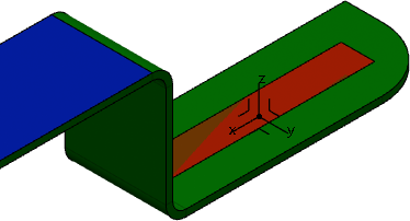
Creating Constraints Areas

You can add outlines and restricted areas of spatial and technological constraints to your flexible circuit board.

Note: When importing an IDF file, each constraint area belongs to a separate body under the PartBody node.

This task shows you how to:

Create a Constraint Area from a Face

You can create a constraint area on an entire face.

  1. From the Edition section of the action bar, click Constraint Area .
    The Constraint Area dialog box appears. By default, the last type of constraint area you created is selected and its name appears in the tree.
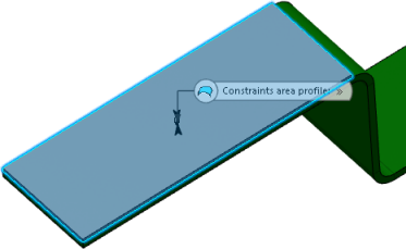
  2. In the 3D area, select a board face.

    Tip: You can select several faces.


    The name of the selected face appears in the Profile box.

  3. In the Type list, select a constraint type:
    Type nameDescription
    ROUTE_OUTLINE An area where routing electrical connections is allowed.
    PLACE_OUTLINE An area within which component placement is allowed.
    OTHER_OUTLINE Additional area type defined by an outline, cutouts, and a thickness.
    VIA_KEEPOUT An area within which placement of vias is not allowed.
    PLACE_KEEPOUT An area where component height is limited.
    PLACE_REGION An area within which placement is limited to certain types of component.
    ROUTE_KEEPOUT An area where routing electrical connections is not allowed.
  4. Set the corresponding parameters, and then click OK.

  • The board is colored according to the selected constraint type.
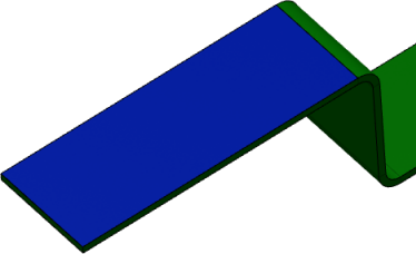
    Note: Each constrain type has a predefined color that can be modified in your preferences. For more information, see Graphic.
  • In the tree, the name of the type of constraint area you selected is updated.
Create a Constraint Area from a Sketch

You can create a constraint area based on a sketch.

  1. Create a sketch on the board:
    1. From the Edition section of the action bar, click Positioned Sketch .
    2. In the 3D area, select a face.
      The Sketcher app opens.
    3. Draw a profile, and then click Exit App to switch to Flexible Circuit Board Design.

      For more information, see Sketcher Users' Guide: Sketching Simple Profiles.

    The sketch is created.

  2. Click Constraint Area .
    • The Constraint Area dialog box appears. By default, the last type of constraint area you created is selected and its name appears in the tree.
    • The sketch is selected.

  3. In the Type list, select a constraint type:
    Type nameDescription
    ROUTE_OUTLINE An area where routing electrical connections is allowed.
    PLACE_OUTLINE An area within which component placement is allowed.
    OTHER_OUTLINE Additional area type defined by an outline, cutouts, and a thickness.
    VIA_KEEPOUT An area within which placement of vias is not allowed.
    PLACE_KEEPOUT An area where component height is limited.
    PLACE_REGION An area within which placement is limited to certain types of component.
    ROUTE_KEEPOUT An area where routing electrical connections is not allowed.
  4. Set the corresponding parameters, and then click OK.

  • The board is colored according to the selected constraint type.

    Note: Each constrain type has a predefined color that can be modified in your preferences. For more information, see Graphic.
  • In the tree, the name of the type of constraint area you selected is updated.