-
In the
Verification section of the
action bar,
click
New Camera Viewer
 . .
The following items
appear:
- The
Camera
Viewer panel.
- A Camera Viewer
thumbnail.
-
In the
Camera Viewer
panel, select:
- Enable Camera Mounting in viewer
- the part from which you want to
view the action, and
- Mount to Selection in the
viewer.
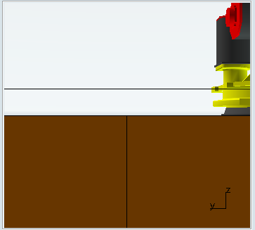
The viewer shows the data from the
viewpoint of the camera location.

-
In the
work area,
zoom in to view a part of interest.
-
Click
New Camera Viewer
 again. again.
A new Camera Viewer panel and Camera Viewer thumbnail appears; the
image in the viewer shows what is in the current work area. 
-
In the Camera Viewer dialog box, select Enable Camera Tracking, and then select the part.
The camera viewer
focuses on the part.
-
Create a third camera viewer that focuses
on a part and also has a camera mount.
-
Deactivate second viewer by right-clicking
on the thumbnail and selecting
Remove from Current
Scenario.
The viewer is deactivated; the associated
thumbnail is unchecked.
-
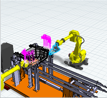
Create another camera probe, and in the
Camera Viewer panel, click
Hide / Show Camera
 so that the camera appears in the
work area,
then snap the
Robot
to the camera. Use the
Robot
to move the camera. so that the camera appears in the
work area,
then snap the
Robot
to the camera. Use the
Robot
to move the camera.
You can choose a
Perspective
 or conical projection, or a
Parallel or conical projection, or a
Parallel
 or cylindrical projection. or cylindrical projection.
- A conical camera is equivalent to a standard camera, with a non-zero
focal length. Parallel lines in the camera line of view appear to intersect at
the same point. Perspective cameras are used in most cases since they are close
to the human vision.
- With a cylindrical camera, parallel lines never appear as
intersecting. These cameras are used to define architectural viewpoints. In a
cylindrical projection, the zoom factor determines the scale of view. The focal
length is irrelevant.
Use the
Robot
for pan or tilt.
|