-
Select the logical components to be placed in the diagram view.
-
From the Diagram section of the action bar,
click Generate Automatic View
 . .
-
In the Selection Direction dialog box, select which ports/interfaces will be taken into account to place the connected components:
- All: All the ports/interfaces
- In: Ports/interfaces receiving a signal
- Out: Ports/interfaces emitting a signal
- InOut: Ports/interfaces receiving and emitting a signal
- NoDirection: Ports/interfaces exposing a variable
-
Click OK.
- In the Sheet dialog box, enter a name for the sheet.
- In the View dialog box, enter a name for the duplicate diagram view.
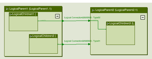
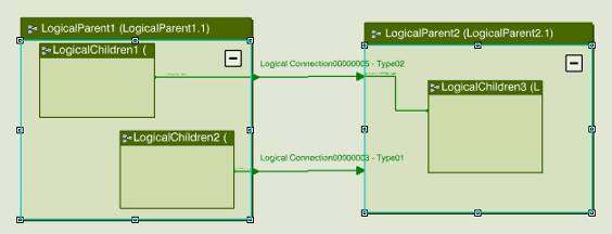
The diagram view is generated and contains the selected component and all its connected components. Only the parent component is visible when the diagram view is generated. 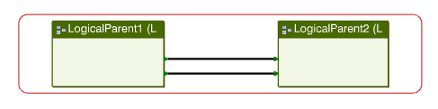 - To display children components, select a parent component and click Go Down
 . .Note:
When routes cannot be displayed, they are highlighted in red.
The selected component is replaced by its children. 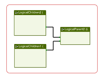
|