-
To place the port, right-click the symbol at the desired location and select Display Port In View
 . .
Note:
This command is also available from the context toolbar.
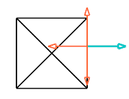
Arrows allowing you to select a direction are displayed.
 -
Select a direction.
The Ports dialog box appears.
- If needed, you can filter the ports:
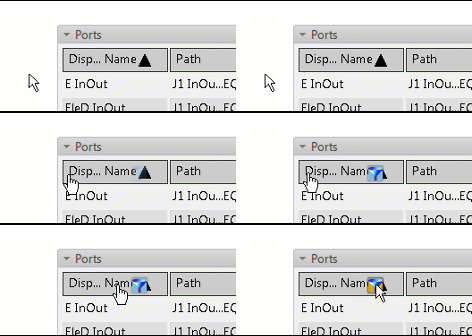
- Hover the pointer over the column to be filtered and click
 . .

- Enter one of the following criteria in the Display Name box:
You can also select the filter from the list. For each column, it references the five previously applied filters followed by all the available values.
- To display only elements beginning with abc, enter abc*
- To display only elements containing abc, enter *abc*.
- To display only elements ending with abc, enter *abc.
Note:
The filter can be removed by clicking Clear Filter  . .
- In the list, double-click a port.
Note:
If the Lock pins multi representation option is selected in
, the Ports dialog box only displays pins which are not represented in a drawing.
The connection point is mapped with a port and displayed on the symbol. If a representation is defined in the Data Setup Default Schematic Port Representation resource, it is placed in the diagram view.
|