The Tree

The tree displays the structure of your system.

This page discusses:

Root Nodes

Functional & Logical Design is a multiroot app. It enables you to display and connect (with implement links) objects from four categories.
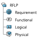
RFLP
The RFLP root node displays the four categories of your system.
See Managing RFLP Systems
Requirement
Displays the requirements the product must fulfill.
See Working with Requirements
Functional
Displays the services (functions) the product must provide.
See Defining Functions and Logical Components
Logical
Displays the logical architecture that is needed to provide the services (functions) of the system.
See Defining Functions and Logical Components
Physical
Displays the physical architecture of the product.
See Working with Physical Systems

Implement Relations

Implement relations are displayed in the implementing object.

Implement Relations
This folder stores the implement links.
See Defining Traceability with Implement Relations
Implement
This final node represents the implement link between two objects.
See About Implement Relations

Connections

Connections are displayed in the tree, with their types (for a connection between logical components) or with their flows (connections between functions).
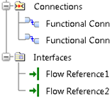
Table 1. Functional Connections
Functional Connections
This folder stores the functional connections.
See Working with Connections
Interfaces
Displays the flows of the functional interfaces.
See Connecting Functions or Logical Components with Interfaces
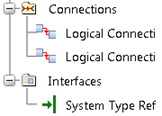
Table 2. Logical Connections
Logical Connections
This nodes stores the logical connections.
See Working with Connections
Interfaces
Displays the types of the logical interfaces.
See Connecting Functions or Logical Components with Interfaces