

Set Up the Model for an Internal Flow Simulation
-
From the Setup section of the action bar,
click Model Setup
 .
.
-
Optional: Include the effects of heat transfer from solid parts by doing
the following:
- Select Include heat transfer from solid parts.
- Expand the Solid parts section that appears, and select one or more solid parts from the tree.
-
Right-click one or more parts and select Assign
material.
Note: You can assign the same material to multiple solid parts at the same time.
-
From the Solid section dialog box that appears, click
 .
The Material Palette opens.
.
The Material Palette opens. - Select a material, and click OK.
-
Specify the fluid for the simulation by doing the following:
-
From the Fluid material options, click .
The Material Palette opens.
-
Select a
material,
and click OK.
For more information about using the Material Palette to search for materials, see About the Material Palette Interface.
-
From the Fluid material options, click
-
Indicate where the fluid flows by doing the following:
-
Click
 on the Regions section.
-
Select the geometry support.
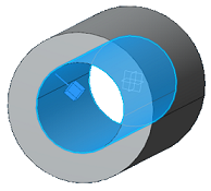
Select a face on the surface that encloses the cavity that will be filled by the fluid; for example, the inner wall of a pipe. In some simulations, this surface is where you will later apply the wall boundary condition or co-simulation interaction for an FSI simulation. You can select a face group to define this support.
If your model has separate fluid volumes, repeat this process to define a fluid region for each one.
A glyph is displayed in the model to show the location of the fluid.
- Optional:
Click Flip direction to change the side of the surface on
which the fluid flows. For example, the glyph in the figure below shows that the
fluid is located inside the pipe.
-
Click
-
Specify the location of any openings in the fluid domain:
Note: At this stage, you do not differentiate between inlets and outlets. This information is added later in the process, when you define flow conditions as part of the scenario.
-
Click on the Openings section.
-
Select the geometry support.
Select a closed loop as the geometry support. In the figure below, the circular inner edge of the pipe opening is selected. You can select an edge group for this support.
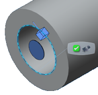
A circular disc glyph shows the location of the inlet or outlet opening. - Repeat steps a and b to select as many openings as required in the model. For example, a car's exhaust manifold might have four inlets and one outlet for five openings.
-
Click