-
From the
Manufacture section of the
action bar,
click
Defines an injection point
 . .
-
Define the pulling direction to compute an injection point. To do
so, define any of the following:
- An axis system: Lets you use the axis to specify a pulling
direction.
- Draft properties: Lets you use the pulling direction
specified in the draft properties.
- Injection point: Lets you use the pulling direction defined
for the selected injection point.
- Z direction of the selected axis system: Lets you use the Z
direction of the axis system of a 3D Part as a pulling direction. By default,
this option is active when both, an axis system and the draft properties, are
not defined.
The respective icon, with a green mark at the upper right
corner, appears in the
Injection Point dialog box.
-
Select a reference surface, curve, plane or point.
The icon
 is replaced by the symbol of the reference element, with a
green mark at the upper right corner.
-
Click the edge, the surface or the vertex to locate an injection
point.
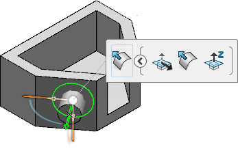
An injection point is located with the
Robot
attached to it. By default:
- On a surface, the injection point position is defined by its
direction, represented by a green arrow, and the pulling direction. The
position of the injection point is the projection of a normal to the surface
onto the plane perpendicular to the pulling direction. The injection point can
be moved only on this surface.
- On a curve, the injection point position is defined by its
direction, represented by a green arrow and the pulling direction. The position
of the injection point is the projection of a tangent to the curve onto the
plane perpendicular to the pulling direction. The injection point can be moved
only on this curve.
-
Drag the
Robot
to move the injection point along the surface or the curve.
-
Click the injection point and select any of the following on the
context toolbar:
- Normal to Pulling Direction
 : Lets you orient the injection point along the normal to
the pulling direction. : Lets you orient the injection point along the normal to
the pulling direction.
- Normal to Surface
 : Lets you orient the injection point along the normal to
the surface. : Lets you orient the injection point along the normal to
the surface.
- Z Direction
 : Lets you orient the injection point in the Z-direction
of the reference axis system. : Lets you orient the injection point in the Z-direction
of the reference axis system.

-
In the
Injection Point dialog box, select the
Simulation Part Body
 check box to create a new simulation part body, used by the
simulation app(s). check box to create a new simulation part body, used by the
simulation app(s).
A
Simulation PartBody node, containing an
assembly of the body selected as a reference geometry for the injection points
and the
set of gates node is added to the tree.
-
In the
Diameter box, enter the diameter of the gate.
-
Click
OK.
An injection point is created on the defined position.
Notes:
- You can apply an injection point only to a 3D part.
- You can create only one injection point at a time.
|