Create a Join Feature
You can use Join to create join features on the associated bodies.
-
From the
Manufacture section of the
action bar,
click
Join
 .
.
The Join dialog box appears.
Important: By default during the creation of the join, the Head and Thread are selected. If the active body is the result of a divide and its associated non-active body is present, the associated body is automatically selected as the entry in the Body to join box. Otherwise this box is blank. During the join creation, this box can be cleared by clicking Head or Thread to deselect them. In this case, the join feature will be a head or thread depending on which button is set; the associated join feature cannot be created afterwards.
By selecting both Head and Thread options, the Body to join box is re-activated. And you may need to select a body in the Body to join box.
Once you click OK, neither the Body to join box nor the Head and Thread options can be changed when editing them. When the Join is edited, the Body to join box will display the name of the associated body in gray color.
-
Select the point in the center of the plane as the
Sketch for the
Screw Positions.
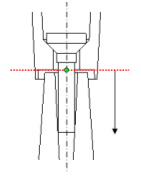
At each non-construction point defined in the sketch, a screw will be positioned. The tip of the arrow points to the body that will be the thread.


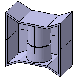
In this case, the lower body has the head geometry constructed within it. While the upper body has the thread geometry. By either clicking on the arrow or clicking Reverse Direction, the tip of the arrow will be reversed, and therefore the geometries will be the opposite from what was described (i.e. the lower body contains the thread geometry while the upper body contains the head geometry).
- Define the parameters in the Screw, Head, Shank, Clamp, and Thread tabs.
-
Click
OK.


