Creating Projections | |||
| |||
-
From the section of the action bar, click Projection
 .
.
- In the Projected box, select one or several wireframe elements.
- In the Support box, select a support.
-
Select the Projection type.
Option Description Normal 
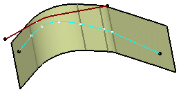
Projects the element normal to the support. 
Along a direction 
Projects the element along a direction. You can define the direction by - selecting a line,
- selecting a plane whose normal will be the projection direction, or
- selecting an X, Y, or Z component or robot direction in the context menu.

- If more than one result is possible,
- select Find Nearest Solution check box to keep the nearest projection, or
- deselect Find Nearest Solution to choose a solution in the
Multi-Result Management dialog box.
Important: If the elements have the same distance to the support, an error message is issued. The distance corresponds to the maximum distance between a point of the projected element and its projection onto the support.
- Optional:
Select an Extrapolate on support mode to extrapolate the
projected wire.
Option Description None The projected wire is not extrapolated. 
Tangency Extrapolates the wire's extremities in tangency to the surface boundary. 
Curvature Extrapolates the wire's extremities in curvature to the surface boundary. 
Warning: - Extrapolating projected closed wires and points is possible but will provide no
difference.

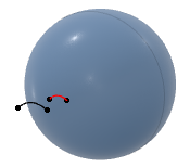
- Extrapolating a wire onto a closed support surface, for example a sphere, is not
possible and will cause an error.

- Extrapolating projected closed wires and points is possible but will provide no
difference.
- Optional:
Select a Smoothing option.
Option Description None Deactivates the smoothing result. With support surface: the smoothing is performed according to the support. As a consequence, the resulting smoothed curve inherits support discontinuities.
Tangency Enhances the current continuity to tangent continuity. Curvature Enhances the current continuity to curvature continuity. If Tangency or Curvature is selected, the following options are available:
Option Description Deviation Specifies the maximum Deviation for tangency or curvature smoothing. Note: For curvature vertices, the topology is automatically simplified by merging cells with curvature continuity.3D Smoothing Smooths the projected element without specifying any support surface. The result has a better continuity quality, however, it does not lie exactly on the support. Tip: Select the Tolerant laydown option in Me  > Preferences > App Preferences > 3D Modeling > 3D Modeling Core
> Generative Shape Design, General
tab, Tolerant Modeling
section.
> Preferences > App Preferences > 3D Modeling > 3D Modeling Core
> Generative Shape Design, General
tab, Tolerant Modeling
section.3D Smoothing cleared 3D Smoothing selected 
