-
From the Manufacture section of the action bar, click
Thread/Tap
 . .
The Thread.x dialog box appears.
-
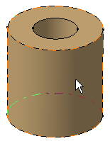
In the Support face box, select the cylindrical surface.

Note:
Thread and tap definitions do not depend on the polarity of the
cylinder geometry. The Thread/Tap capability lets
you specify whether you want to create a thread or a tap by selecting
the appropriate option.
Note:
If you prefer to create a tap, select Tap
 . .
-
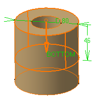
In the Limit face box, select the face up to which
thread should be created..

The Reverse Direction
 or the
arrow in the work area lets you reverse the thread direction, if needed. or the
arrow in the work area lets you reverse the thread direction, if needed.
-
Select the required thread standard.
Notes:
- As you are creating a thread, you cannot modify the thread diameter
value. If you were creating a tap, you could modify it.
- If you set standards files in both
Data Setup
and installation directory, the standard files set in
Data Setup
are given priority.
- The standards set using
Data Setup
are available only in the online mode.
-
In the
Thread Depth box, enter a value.
The Support Diameter and
Support height boxes are dimmed. They are merely
informative.
-
In the
Pitch box, enter a value as the pitch value to
define the distance between each crest.
-
Select
Right-threaded or
Left-Threaded option.
- Optional:
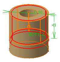
Click Preview.
Red lines provide a simplified representation of the thread.

-
Click
OK.
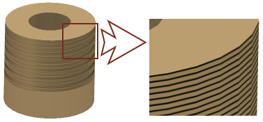
A texture representing thread is displayed on the cylindrical
surface. It is a symbolic representation.

The thread (identified as Thread.xxx) is added to
the tree. The corresponding icon is specific to this feature. Diameter, depth and pitch values
appear under the Thread node in the tree.
Notes:
- If you create a tap, in the tree, the app identifies it as Thread.x, but
displays a specific icon.
- In the App Options panel, you can click 3DMaster query
 and move the mouse pointer over a hole or thread in the work area to view technological information in the tooltip. and move the mouse pointer over a hole or thread in the work area to view technological information in the tooltip.
|