The Tree | ||
| ||
Tree Structure
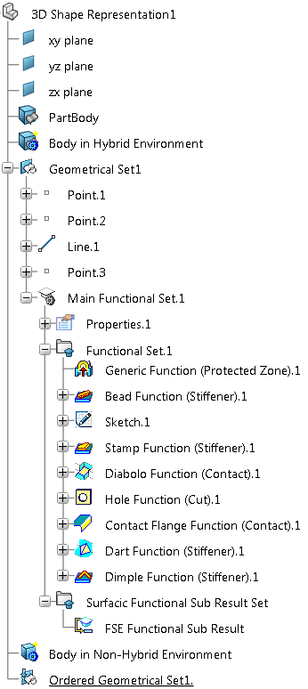
The following picture represents a typical tree in Functional Shape Design

Symbols
The various symbols used to identify the elements created in the tree are described in this reference section.
|
|
3D Shape Representation |
| Body |  | Working Zone Function | |
| Geometrical Set | Text with Leader | ||
| Ordered Geometrical Set | Flag Note with Leader | ||
| Surfacic Functional Set | View From Reference | ||
| Functional Set |
Note:
As shown in the tree structure above, depending on the chosen environment type:
- The gear icon masks the Body icon
 when Enable hybrid design inside part bodies and bodies option is cleared
 - The gear icon masks the Part Body icon
 when Enable hybrid design inside part bodies and bodies option is selected
For more information, see the Part Design User's Guide.
|
|
Point | Plane |
|
|
|
Line |  | 2D Profile |
 | Bead Function |  |
Contact Flange Function |
 | Stamp Function |  | Dart Function |
 | Diabolo Function |  | Dimple Function |
 | Hole Function |  |
Generic Function |
|
|
Sketch |
|
|
Draft Analysis | Surface Curvature Analysis |
|
|
Axis System | User Feature |
|
|
|
Power Copy |  | FSE Functional Set Result |