You can use Spot Fastener Creation
to instantiate flexible fasteners. Choosing fastener references, locations and fastening
stacking parts can be done in any order.
You can specify the stacking by selecting a bundle.
To help you
specify it, you can also use Autostacking. For more
information, see Specifying a Stacking Using Autostacking.
From the Fastener section of the action bar,
click Spot Fastener Creation.
By default, the stacking selection mode is on.
If Auto Bundle Location is selected, an existing bundle with
specified stacking is used for instantiating the fastener. If there is no bundle, a
bundle is created. If Auto Bundle Location is cleared, search for
a bundle using a search capability. For more information, see Specify Options.
The top area of the dialog box displays the list of the stacking parts. This list is
composed of three columns:
Pilot: indicates the pilot part. "P" appears in the first
row as the first part is always the pilot part.
Important:
You cannot
specify as pilot part a part other than the first part.
Fastened Parts: indicates the instance names of the
selected stacking parts.
In the tree, or in the 3D area, select
the parts to define the stacking.
Use the different commands to organize the stacking. For
more information, see About Organizing Stackings.
Tip:
To locate stacking parts easily, right-click a stacking part and select
Center Tree or Refame On.
Locate the Instances
You can select points to locate flexible fastener instances.
Click Points.
Select one of the following:
Points
Geometrical sets: all the points inside the selected geometric set are considered
as fastener locations.
Recommendation:
Select points from a single skeleton for one stacking group
so as to obtain one skeleton per stacking group.
Optional:
Select Smart Projection.
Possible correct projections are identified. They are calculated according to
the selected stacking parts. For more information, see About Smart Projection.
To exit the geometry selection mode, do one of the following:
Click Exit button.
Click any stacking parts from Stacking.
Click the reference editor to enable the reference selection command.
Specify the Fastener Reference
You can select the fastener reference in multiple ways.
Do one of the following:
In the 3D area,
select a fastener reference.
In the tree, select a fastener reference.
If you clicked Reference Editor, the reference selection wizard is displayed. You
can then select a reference in session, select a reference from
Catalog., or you can
search for a reference.
Optional: To verify the reference properties, click View
Reference Properties.
Note:
You cannot modify these properties.
Specify Options
Expand the Options frame.
Optional:
To project the fastener location on the pilot part, select Project on
Pilot Part.
Optional:
To restrict the location to selected points, select Restrict to point
selection. If this option is cleared, you can select any geometry.
In this case, an explicit fastener is created.
Optional:
Select Auto Bundle Location.
An existing bundle with specified stacking is used for instantiating the
fastener. If there is no bundle, a bundle is created. If this option is cleared, you
must either select a bundle manually, or search for a bundle using one of the following commands:
Search from Session: the bundles
for the selected stacking are searched in the session.
Search from Database: the
bundles for the selected stacking are searched in the database.
Optional:
Select Allow duplicate stack part selection to be able to
select the same part twice in the stacking frame. If this option is cleared, you cannot
select the same part again.
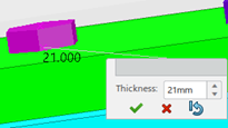
For example, you can select Thickness to preview the
thickness computed at the current location for the current stacking.The Computed Stacking Thickness Is Displayed in Black.
Tip:
To enforce a thickness value, click the computed thickness value
and enter the new value. The
enforced value is displayed in yellow. . To
retrieve the computed value, click Reset.
Specify the Bundle Location
Expand the Advanced Options frame.
Optional: By default, the bundle is positioned under the common father
node. Clear Common father node if you need to use the bundle
under the active product node.
Apply Different Colors to the Parts
Optional: Expand Legend.
Optional: Select Activate 3D Coloring to apply
colors to the different parts in the 3D area.
Select either of the following:
Pilot Non-Pilot : applies the different colors to the pilot
part and other parts in the stacking.
Primary Secondary: applies the different colors to the
parts fastened by the primary fastener and the parts fastened by secondary
fasteners.
The colors are applied according to the color schemed defined. For more
information, see About Colored Stacking Parts.
 . For more
information, see Specifying a Stacking Using Autostacking.
. For more
information, see Specifying a Stacking Using Autostacking. .
By default, the stacking selection mode is on.
.
By default, the stacking selection mode is on.
 .
.
 : the bundles
for the selected stacking are searched in the session.
: the bundles
for the selected stacking are searched in the session. : the
bundles for the selected stacking are searched in the database.
: the
bundles for the selected stacking are searched in the database.
 The
enforced value is displayed in yellow.
The
enforced value is displayed in yellow. 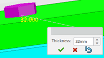 . To
retrieve the computed value, click
. To
retrieve the computed value, click  .
.