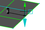
About Moving Mesh Lines | |
| |
- You move the control points on a mesh line by dragging the line (or by editing its X, Y and Z coordinates).
The direction or plane in which you can drag a control point is determined by the constraint selected in Support in the Control Points dialog box.
- As you drag a mesh line, all the control points on this mesh line will move along the same constraint.
- The distance that the control points move on the mesh line you are dragging is determined by your selection in the Control Points dialog box in the Diffusion area only (Constant Law, Linear Law, Concave Law, Convex Law, Bell Law).
- The distance that the control points move on any other selected mesh line is determined by your selection in the Control Points dialog box in the Cross Diff area (Cross Constant Law, Cross Linear Law, Cross Concave Law, Cross Convex Law, Cross Bell Law).Note: The cross diffusion laws will be available only if Mesh Only and any of the diffusion laws are selected.
- When Link Laws is selected, Diffusion becomes unavailable, the mesh line you drag is set to Constant Law and control point movement on any other selected mesh lines is determined by your selection in the Cross Diff area.
Tip: For maximum control, leave Link Laws unselected.
Note:
After moving the selected mesh lines, you can choose another cross diffusion law which will be directly applied to the selected mesh lines.
In each of the following examples, the Constant Law diffusion law is selected. The examples highlight the different behavior of control points on 5 selected mesh lines when different cross diffusion laws are selected in the Cross Diff area. The illustration below shows the starting point of each example; the control points of the 5 selected mesh lines can be seen highlighted in blue and the end mesh line is the line which is being dragged. 
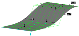
- Cross Constant Law
- The control points of the 5 selected mesh lines have all moved through the same (constant) distance:
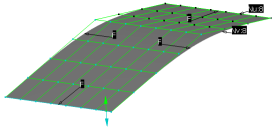
- Cross Linear Law
- The control points of the 5 selected mesh lines have moved by a linearly decreasing amount and now form a straight line:
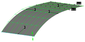
- Cross Concave Law
- The control points of the 5 selected mesh lines have moved by a non-linear amount and now form a concave line:
- Cross Convex Law
- The control points of the 5 selected mesh lines have moved by a non-linear amount and now form a convex line:
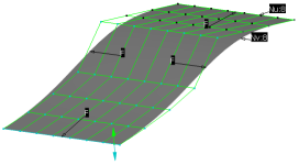
- Cross Bell Law
- The control points of the 5 selected mesh lines have moved by a non-linear amount and now form a bell shape line:
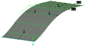
Note:
When using another law than Constant Law, the point belonging to the handle and enclosing the point of maximum load is highlighted by a rectangle.
