-
From the View section of the action bar click Mirror
Analysis
 . .
The Mirror Analysis dialog box appears.
-
To select the elements and analyses to mirror, do one or a combination of the
following:
- In the work area, select the elements; Ctrl-click to
multiselect.
- In the tree, select the part node or individual elements under
it; Ctrl-click to multiselect.
- In the tree, select the geometrical set or individual elements
under it; Ctrl-click to multiselect.
- To select the elements of the
pre-defined display lists:
-
Right-click the
Elements box
and select
Display
Lists.
The
Display Lists
Selection dialog box appears.
- In the
Display Lists
box, select the required list.
-
Click
OK.
Notes:
- Use the
Active Display
List
context menu
command to select the elements of the current active display list.
- Use the
Change Display
List
context menu
command to replace the selected list.
If you select the part node or the geometrical set, all valid elements under it are
selected.
The selected elements are listed in the Elements dialog
box.
-
Select the Symmetry Plane.
Symmetry plane is the plane about which the mirror takes place. By default
zx plane is selected. You can select or create a different plane
for symmetry using the context menu options: - Create Plane
- XY Plane
- YZ Plane
- ZX Plane
-
Click Display plane
 . .
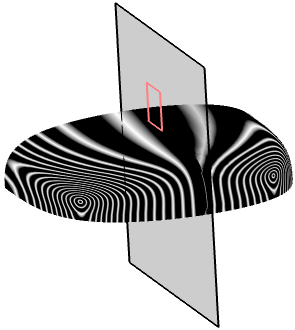
The mirror plane appears. Also the mirrored elements are displayed along with any analysis.
 -
Click Display mirror tags
 . .
The mirrored elements and their analysis are displayed in the predefined color
defined in the Feedback color option in
> FreeStyle Shape Design, General
tab, Mirror analysis options
section. By default, gray color is selected. The mirrored elements are displayed along
with the analysis in the default feedback color. 
-
Click OK.
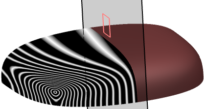
- Change the default color to brown in .
- To update the graphical properties, right-click Mirror
Analysis.X and select Mirror Analysis.X object >
Update graphical properties.
The mirrored elements are displayed in brown color.
 Notes:
- If only a surface is selected and the mapping analysis applied on it is not selected, then only the surface is mirrored and not the mapping analysis.
- If a mapping analysis is selected, then the analysis and the surface are both mirrored.
- If a surface with rendering material is selected, the rendering material is mirrored only if the
material is directly defined on the surface or the part. The surface is always
mirrored.
- You can update the graphical changes by right-clicking the mirrored part and selecting Update graphical properties.
- The global FreeStyle Shape Design analyses are not supported as input for mirroring.
|