Managing the Robot and Axes

Creating Masks

You can create a mask, that is a 3D box in which the geometry is displayed, either using coordinates or position and dimension.

This box limits the display of geometry but does not cut it. It is limited by six planes and each edge of the box is parallel to the current axis system.

This task shows you how to:


Before you begin: Create a 3D shape containing geometric elements.

Create Masks Using Coordinates

You can create a mask by defining the coordinates.

  1. From the Creation section of the action bar, click Mask .
    The Mask Definition dialog box appears.
  2. In the Mask Type list, select Coordinates.

    The following picture shows how the mask is computed:
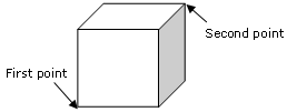


  3. In the Point 1 box, select a first point.
  4. Select a second point.

    The 3D box appears, it has no handles:
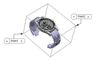


    Minimum and maximum coordinates are displayed and the boxes are unavailable.

  5. Alternatively, you can enter minimum and maximum coordinates of the box.

    The 3D box appears along with the handles:


  6. Use the handles to translate each face of the box along the current axis direction and resize the mask box.


  7. In the Axis System box, select the desired axis system.

    By default, it is automatically set to the current axis system but you can choose an another axis system or use the context menu to create a new one.

  8. Click OK to create the mask.

    All the elements completely outside of the 3D Box are not displayed. The elements partially outside of the 3D box are displayed and the elements just on the face of the 3D box are included in the 3D box.
Create a Mask Using Position and Dimension

You can create a mask by defining the position and dimension.

  1. Click Mask .
    The Mask Definition dialog box appears.
  2. In the Mask Type list, select Position & Dimension.

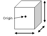
    The following picture shows how the mask is computed:


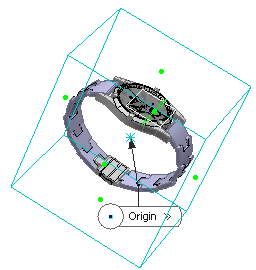
  3. Select a point as the origin of the box or use the context menu to create a new one.

    The point's coordinates are displayed and the boxes are unavailable.

  4. Enter the minimum and maximum coordinates of the point.

    In both cases, the 3D box appears along with handles:


  5. Use the handles to translate each face of the box along the current axis direction and resize the mask box.


    Important: If you drag the face, the other side of the side is symmetrically moved to the other position.
  6. In the Axis System box, select the desired axis system.

    By default, it is automatically set to the current axis system but you can choose an another axis system or use the context menu to create a new one.

  7. Click OK to create the mask.