-
From the Creation section of the action bar, click Styling Sweep
 . .
-
Select the sweep type.
-
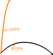
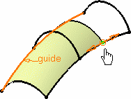
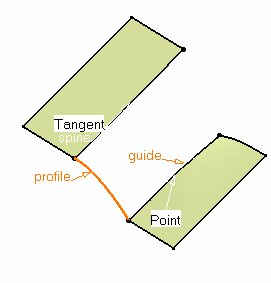
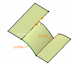
Select curves as profile, spine, and guide as required.
Styling sweeps cannot be created using canonical profiles.
- Optional:
Click <<Settings to define the parameters.
- Order V: Maximum V order, the U order being defined by the
profile curve's order.
- Max. deviation: Maximum deviation between the exact surface
and the resulting surface, in order to decrease the number of control points and
segments on the resulting swept surface.
- Optional:
Click the values to edit them.
-
Click Selection>> , then
Display>>, and information to
display the tags.
- Optional:
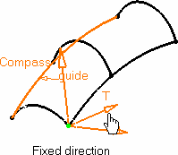
Activate the moving frame.
The moving frame is used to define how the profile is swept along
the spine.
-
To edit the moving frame, do one of the following:
- In the work area,
click the moving frame to change its type.
- Shift+ click to move back.
- Right-click to display the context menu.
These moving frame types are available:
The current type is displayed when passing the cursor over the moving frame. You can
move the frame along the spine using the handle at the moving frame's origin.
- Optional:
For the Fixed direction and Tangent to
contour types, set the direction according to the Robot orientation definition by doing either of the following:
- Drag and drop the Robot onto the geometry.
- Use the quick Robot orientation capability (F5).
The Robot should not be tangent to the curve.
- Optional:
Activate the limit points to redefine the surface limits on the
spine/guide.
Thes limit points show up only when the surface extends beyond the
reference profile when selected, and are limited by the spine or guide's length.
- Optional:
Right-click a limit point to open the context menu.
-
Click OK.
 indicates that the element has one support. indicates that the element has one support.-
 indicates that the element has more than one support. Right-click the tag to display the available supports and select the one you want to use. indicates that the element has more than one support. Right-click the tag to display the available supports and select the one you want to use.
|
 is active in the App Options panel. Note: The continuities are available depending on the selected sweep type and the geometry itself.
 in the App Options panel to display the handle on the surface and modify its limits.
 indicates that the element has one support.
 indicates that the element has more than one support. Right-click the tag to display the available supports and select the one you want to use.