Creating Geometrical Tolerances | ||
| ||
-
In the Geometrical Tolerance dialog box, perform the
following operations:
- Under Add Tolerance, click the required tolerance indicator.
-
Under Edit Tolerance, select the tolerance
indicator.
You can select the Remove Line check box to remove the selected line. This option is unavailable if the selected tolerance line is the only one.
- In the Edit Tolerance box, enter the tolerance value.
-
In the Reference boxes, add references.
You can add multiple references.
- Select an engineering symbol.
-
In the Auxiliary Feature Indicators list, select
a local indicator.
You can select intersection, orientation, collection, and direction planes as local indicators.
Note: You can add maximum three non-identical local identifiers for a single tolerance. - In the Auxiliary Feature Text Indicator box, add an indication text.
-
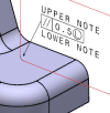
In the Global Text Indicators boxes, add an
upper and a lower text.
You can also select engineering symbols.