Functional Tolerancing

Functional Tolerancing: Approach and Methodology

The functional tolerancing features help the designer to define the functional dimensioning and tolerancing of the parts of a mechanism, according to the ISO or ANSI-ASME standards.

The approach is based on the expertise and the knowledge of the designer about the mechanism, expressing its engineering intents and need. Based on it, the Tolerancing Generation automatically generates the geometric dimensioning and tolerancing (GD&T) specifications in a suitable view.

While generating GD&T specifications, each part is studied independently. It does optimize the tolerance values. Tolerances are taken from predefined values and further refined by the designer.

For each of the part, the proposed methodology includes the following stages:

  • Mechanism analysis (common to all the parts)
  • Functional tolerancing in CATIA

This page discusses:

Choice of the Positioning Order of the Parts

The principle consists in identifying a part of the mechanism called the base, on which the other parts are positioned, one after the other. Thus, the mechanism constructed is then positioned in the external environment.

The positioning of a part is blocking of all the degrees of freedom, except the required kinematic mobilities.

The positioning order does not always correspond to the actual assembly order. Because during assembly, the positioning may be temporarily incomplete.

The chosen order must be shared by all the collaborators of the project for consistent tolerancing of all the parts of the mechanism.

It is often required to build blocks that constitute the subsets of the parts fixed together forming a rigid body. Each block has a base and is positioned globally in the mechanism.

There are several possible choices for the base and for the positioning order, which give different tolerancing results.
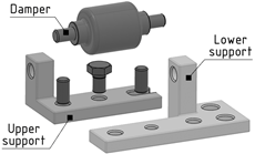
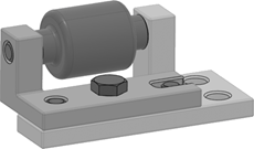
Illustration of the Methodology on a Simple Example

The damper mechanism is made of three main parts: a lower support, an upper support, and a damper.

This mechanism is fixed in the external environment on a plate using two screws.

There are two geometric requirements in the functional specifications of the mechanism (which both apply to each generator of the damper):

  • Orientation between the support plane and the fastening holes of the plate and the top generator of the damper.
  • Distance between the support plane of the plate and the top generator of the damper.


Choice of the Positioning Order of the Parts of the Damper Mechanism

The lower support is the base of the mechanism.

The upper support is positioned on the lower support using two centering pins, and is maintained in position using a screw. There is no remaining degree of freedom.

The damper is positioned on the block made of the upper support and the lower support. There is one degree of freedom in rotation.