Mechanical Interface (MI)
A Mechanical Interface (MI) is a structured set of surfaces of a part that are designed to mate to the other part.
| Surfaces | Description |
|---|---|
Primary surfaces  |
Constraints the most the position of the part when mated to the other part |
Secondary surfaces |
Constraints the most, after the primary ones, the position of the part when mated to the other part |
Tertiary surfaces |
Constraints the less the position of the part when mated to the other part |
Maintain surfaces  |
Maintains the part in the position set by the primary, secondary, and tertiary surfaces when mated to the other part |
The intermediary parts (pins, screws, bearings, etc.) can be managed by defining appropriate clearances.
You can create the MI features in a 3D Shape using one the following commands:
- Mechanical Interface Creation
 : Creation of a MI
feature into the edited 3D Shape.
: Creation of a MI
feature into the edited 3D Shape. - Mechanical Interface Instantiation
 :
: Creation of MI feature from a MI template PLM object into the edited 3D Shape.
MI templates can be created and managed using the Mechanical Interface Templates Captureapp.
- Mechanical Interfaces Reveal
 :
Automatic creation of MI features from copied geometric features (copy as result, copy
as specification, power copy, user feature, etc.).
:
Automatic creation of MI features from copied geometric features (copy as result, copy
as specification, power copy, user feature, etc.).
You can refine the MI features using the Mechanical Interfaces
Assistant
 command. The command verifies the assembly consumption of the interfaces:
- Connected by engineering connections
- Positioned (in front of an opposite MI)
- Not connected or positioned: Connections to other systems or design problems
It also verifies the quality and the completeness of the interface definition as below:
- Identify the useful portion or extension of the functional surfaces:
- Actions: Create, update, edit, or delete the restricted area
- Actions: Create, update, edit, or delete the extended cylinder
- Identify the geometric inconsistencies
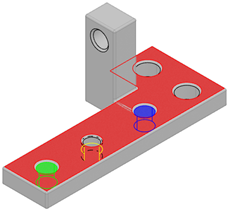
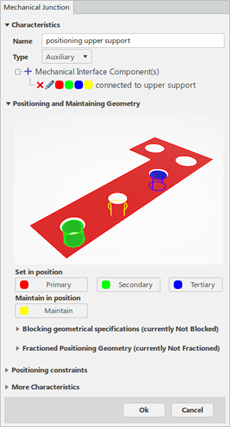
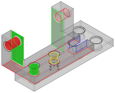
MI Connected to Upper Support
It connects the lower support part to the upper support part through the following features:
- A plane primary contact surface
- A cylinder secondary surface using an intermediary pin mounted with tightening in the hole
- A cylinder tertiary surface using an intermediary pin mounted with tightening in the hole
- A thread maintain surface using an intermediary screw
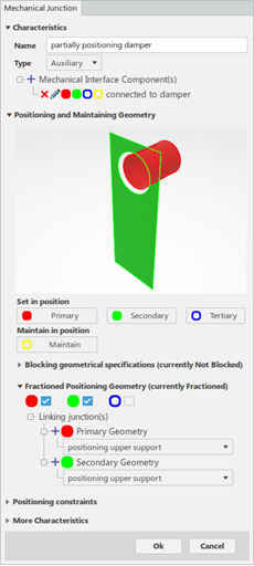
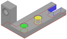
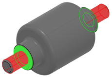
MI Connected to Damper
It connects the lower support part to the damper part through:
- A cylinder primary surface with clearance
- A plane secondary contact surface
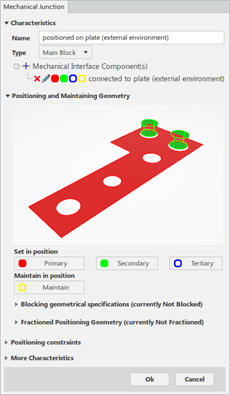
MI connected to plate (external environment)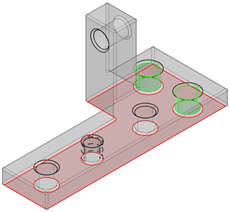
It connects the lower support part to the external environment through:
- A plane primary contact surface
- A cylinder secondary surface with clearance
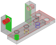
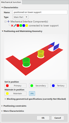
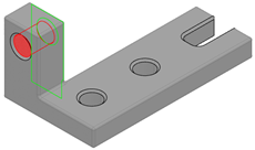
MI Connected to Lower Support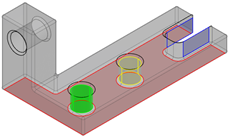
It connects the upper support part to the lower support part through:
- A plane primary contact surface
- A cylinder secondary surface with clearance
- A cylinder tertiary surface with clearance
- A cylinder maintained with clearance
MI Connected to Damper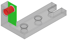
It connects the upper support part to the damper part through:
- A cylinder primary surface with clearance
- A plane secondary contact surface
MI Connected to Upper Support
It connects the damper part to the upper support part through:
- A cylinder primary surface with clearance
- A plane secondary contact surface
MI Connected to Lower Support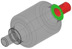
It connects the damper part to the lower support part through:
- A cylinder primary surface with clearance
- A plane secondary contact surface
 command.