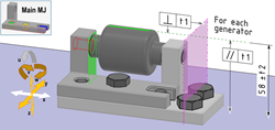
Each part has a main MJ and as many auxiliary MJ as supporting parts or blocks. If a deviation in the position or the orientation of an auxiliary junction brings a risk of failure in the mechanism, it must be constrained in position relative to the main junction. You can specify these positioning constraints by editing the auxiliary MJ. Similarly for an FS, if a deviation in the position or the orientation of an FS brings a risk of failure in the mechanism, it must be constrained in position relative to the main MJ. You can specify these positioning constraints by editing the FS. Damper Mechanism Example: Auxiliary MJ of the Lower Support Part A deviation in position along y or z or in orientation around u, v, or w of the surfaces
of the auxiliary MJ impacts the orientation and distance geometric requirements of the
mechanism. The auxiliary MJ must be constrained in position and in orientation relative to the main
MJ positioned on the plate (external environment). Under Positioning Constraints, you can specify the type of
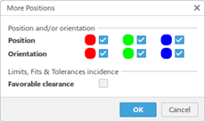
constraint, and indicate if the local clearances of the auxiliary MJ are favorable or not: 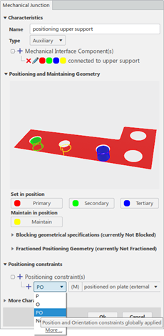 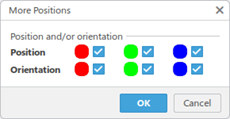 A deviation in position along y or z or in orientation around v or w of the surfaces of the auxiliary MJ impacts the orientation and distance geometric requirements of the mechanism. The auxiliary MJ must be constrained in position and in orientation relative to the main MJ positioned on plate (external environment). 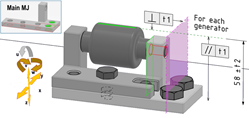 The positioning constraint dialog box allows choosing the appropriate type of constraint, and indicating if the local clearances of the auxiliary MJ are favourable or not:
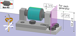
The local clearances of the reference main MJ are unfavorable in that case. Damper Mechanism Example: Auxiliary MJ of the Upper Support Part A deviation in the position along y,z, or in orientation around v or w of the surfaces of
the auxiliary MJ impacts the orientation and distance geometric requirements of the
mechanism. The auxiliary MJ must be constrained in the position and orientation relative to the main
MJ positioned on the lower support. The position and orientation constraints applied to all the surfaces of the MJ with unfavorable clearances (PO(L)) is the appropriate positioning constraint in that case. 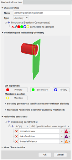 You can indicate which failures might occur if the positioning constraints are controlled
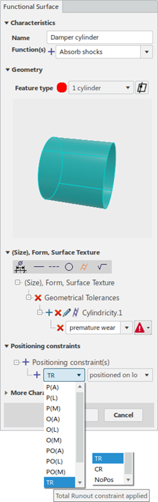
poorly. Damper Mechanism Example: FS of the Damper Part A deviation in the position along z or in the orientation around v or w of the damper
cylinder FS impacts the orientation and distance geometric requirements of the
mechanism. The auxiliary MJ must be constrained in the position and orientation relative to the main
MJ positioned on the lower support and upper support block. Under Positioning Constraint, you can specify the type of constraint and indicate if the local clearances of the auxiliary MJ are favorable or not:
 | ||||||