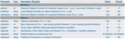
The GD&T are generated based on the following set of parameters:
These parameters are defined in two Excel files (one for ISO standards and one for ASME-ANSI standards). They can be customized (modification of the values and addition of columns). The four Excel files are delivered as a content in a resource directory of the CATIA client installation. They are used until no corresponding data setup physical resources have been defined. The dedicated preferences let you specify the parameters to be used. The failures defined in the positioning constraints of the MJ and FS are inherited by the corresponding generated size and geometric tolerances. All the generated GD&T appear in already existing or newly created views with view ratios appropriate to the size of the 3D parts. In a view, the GD&T applied to the same toleranced feature are grouped together. All the groups of GD&T and individual GD&T are organized to avoid text and symbols overlapping in the view. A capture is created or updated for each MJ and each FS. It displays all the generated GD&T which are applied to the surfaces that define the MJ or the FS. It also displays all the datum features of the datum systems used in the geometric tolerances. The GD&T specifications generated for the previously described MJ and FS features of the damper mechanism are as below: 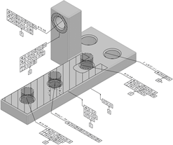 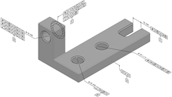 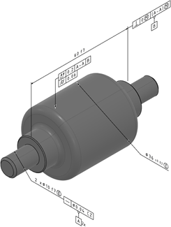 | ||||||