Creating a Datum and Datum Targets | |||
| |||
- Right-click a capture in the tree and select Set Current. All the created annotations will be added to this capture as long as it is current.
-
From the
Annotation
section of the
action bar, click Tolerancing Advisor
 .
.
The Semantic Tolerancing Advisor dialog box appears.
-
Select the four surfaces as shown below on the part. The last
selected surface will support the datum.
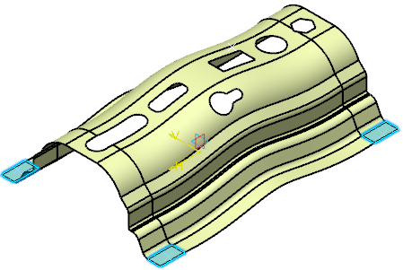
The Semantic Tolerancing Advisor dialog box is updated.
Note: Buttons and options displayed in the dialog box depend on your selection. -
Set Feature type as N geometric features in collection(Nx CZ) and click
Semantic Datum
 .
.
The datum is created.
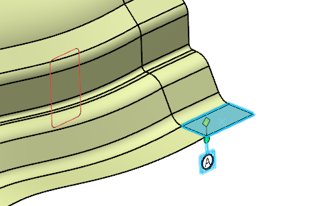
The Datum feature dialog box appears.
Note: The Thread Geometry frame appears only when datum features are a group of thread surfaces. -
Click
Add in the
Datum feature
dialog box.
The Datum Target dialog box appears. Keep the options as is.
Important: The Movable Datum Target frame appears in ASME Y14.5-2009 and ISO 5459-2011 standard context.
-
Select the target points as shown below on the part.
-
Select the first point.
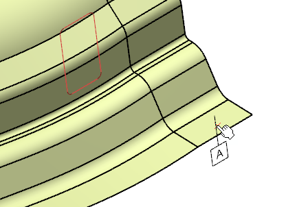
Important: You do not have to click OK in the Datum Target dialog box, selecting another point automatically validates the datum target creation.
Note:The Movable Datum Target frame is editable once a point selected.
Select Movable check box and define a Direction to define how it will be move.
If the Movable check box is selected, the OK button is available for selection only if the Direction is defined.
-
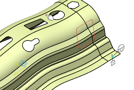
Select the second point.
-
Select the third point.
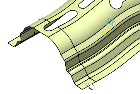
-
Select the fourth point.
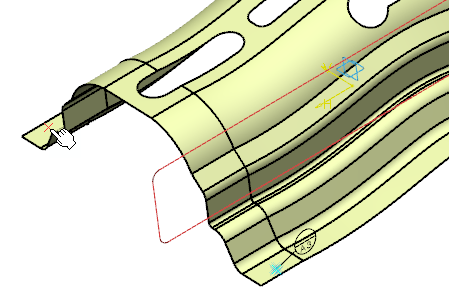
-
Select the first point.
-
Click
OK in the last
Datum Target dialog box to end the datum target
creation.
The Datum feature dialog box is updated.
-
In the
Contacting Feature section of the dialog box, click
[CF].
With this, you can select the datum contacting feature. You can select multiple features. The contacting feature which you select has to be tangent to the datum feature. It must also be on the external material side.
Selection box is enabled. -
Select the required contacting feature.
- Geometry Connection Management is active for selection. You can select this to replace, edit, or rename the current selection
- Unselect option is active for selection. You can select this to clear the selection in the [CF] box.
Note: The datum label is followed by [CF] in all the DRF in which it is included. -
Click
OK in the
Datum feature dialog box.
The datum and datum targets are created in the geometry and tree.
Note: The annotation for contacting feature datum modifier is invalid when the standard of a feature is changed from ISO to ASME using the feature properties.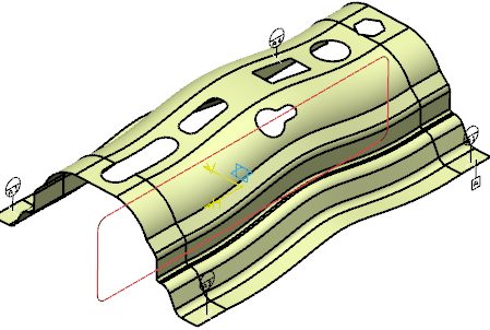
Important: Following operations are not supported: - Pasting a semantic datum or semantic datum target feature created using ISO 5459:2011 in a level which does not support the same.
- Instantiating a PowerCopy that contains semantic datum target feature or geometric tolerance with DRF feature created using ISO 5459:2011 in a level which does not support the same.
- Applying a tolerance schema that contains either a datum target semantic feature, a semantic datum feature, or a DRF feature created using ISO 5459:2011 in a level which does not support the same.
- Importing a tolerancing set that contains either a datum target semantic feature, a semantic datum feature, or a DRF feature created using ISO 5459:2011 in a level which does not support the same.