Using the Local Scope Range

You can set Local for the scope range when handling connections with the Connection Management dialog box as well as verify the consistency of the reconnected annotations with the Scope Range option you selected.

Important:
  • The connection is calculated with respect to the local axis of the geometrical element; not where the point is selected.

  • Constructed geometries are user surface-based that are not taken into account in the reconnecting process, nor affected. Any modification to the geometric components of a user surface involved in a constructed geometry is reflected in the constructed geometry that is updated automatically.

  • Annotations used in a FTA Assembly or a FTA 3D Shape context are supported by the connection manager except for Assembly FTA Presentations features that are generated directly from a 3D shape annotation.


Before you begin: Open a 3D shape containing at least an annotation.
See Also
Using the Unique Scope Range
Using the Global Scope Range
3D Annotations and View/Annotation Planes
  1. Right-click an annotation assigned to a 3D shape, and select Associated Geometry > Geometry Connection Management.


    The Connection Management dialog box appears.

    Note: In Graph of Geometrical Links, the feature linked to the selected annotation is displayed. If the linked feature is in Hide state, the last child feature in the tree in Show state and of the highest priority level is displayed.

  2. In the Scope Range area, select Local.
    Important: The modification to the geometry connection will affect the selected annotation only.
  3. Right-click Geometric Component.x in the Graph of Geometrical Links, and select Connect .
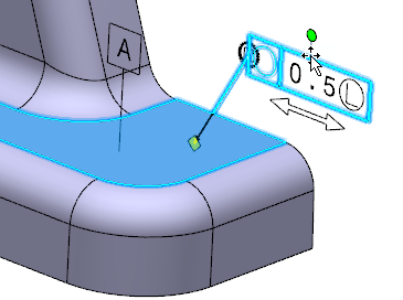
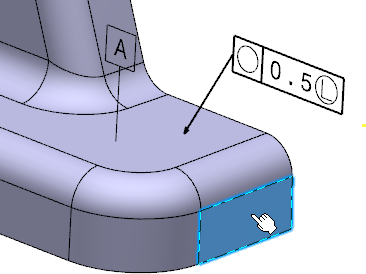
  4. Select a surface that belongs to the part assigned an annotation.


    The Connection Management dialog box appears. A table lists the affected 3D annotations and provides information including:

    • The selected annotation,
    • The effect type,
    • The initial validity of the selected annotation,
    • The current validity of the selected annotation after the reconnecting process is complete.
  5. Click Check Validity to verify the new geometry component is consistent with the selected annotation.
    In the Connection Management dialog box, the selected annotation as well as the related annotations are listed in the table under Annotations.
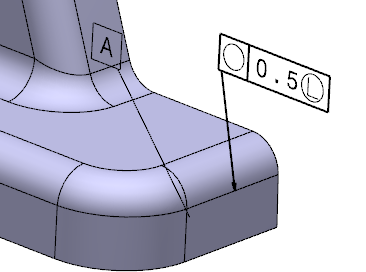
  6. Click OK.
    The annotations are now connected to the new surface.