Generating Dimensions from a Part Design Hole

You can create Part Design Hole dimension from its specifications.


Before you begin: Open an existing 3D shape.
See Also
About Dimensions from Part Design Features
  1. From the Annotation section of the action bar, click Generative Dimension
    The Generate 3D Tolerancing Dimensions dialog box appears.
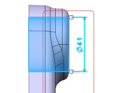
  2. Select the required hole.


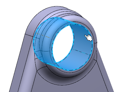
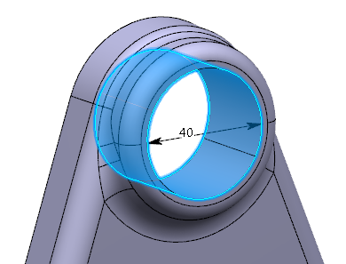
    The hole diameter parameter is displayed in the dialog box as well as on the part.


  3. Select the Diameter parameter in the dialog box.
    You can also select the parameter on the geometry.
  4. Click OK.
    The diameter dimension is created.


  5. Right-click the dimension and select Transfer To View/Annotation Plane.
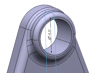
  6. Select Front View.x annotation plane.
    The dimension is transferred.


  7. Drag the dimension.
  8. Right-click the dimension and select Edit Generative Parameter.
    The Parameter Definition dialog box appears. You can modify the hole parameter in the dialog box.
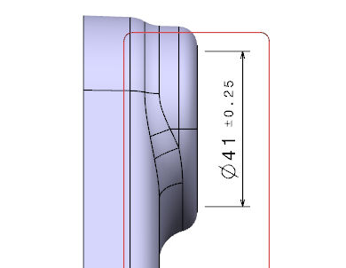
  9. Enter 41mm in the Value box and click OK.
    The 3D shape turns red because it is modified but not updated.

    It is automatically updated. The 3D shape hole and diameter dimension are modified.


  10. Right-click the dimension and select Edit Generative Parameter.
  11. Right-click in the Value box and select the Add tolerance.
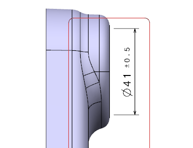
  12. In the Tolerance dialog box, specify the Maximum tolerance and the Minimum tolerance.
    Tolerances are displayed on the dimension.


  13. Click OK in the Tolerance and Parameter Definition dialog boxes.
  14. Modify the tolerances in the Dimension properties in the Object Properties panel to +-0.25.
    Tolerances are updated on the dimension.


  15. Right-click the dimension and select Edit Generative Parameter again.
  16. Right-click in the Value box and select the Tolerance > Edit....
    The parameter tolerances are also updated.
  17. Click OK in the Tolerance and Parameter Definition dialog boxes.