You can create a restricted area
annotation, apply different representation patterns on it, and generate the drawing for
the views displaying the restricted area.
A restricted area annotation allows you to define a delimited surface to be
toleranced.
The restricting area may consist of several elements.
The surface may be defined using Generative Shape Designapp.
From the
Annotation
section of the
action bar, click Restricted Area.
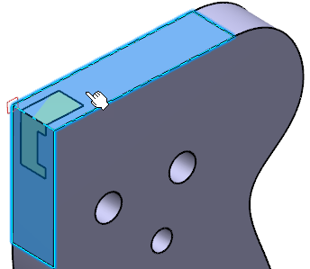
Select the required surfaces to be restricted.
Important:
The Restricted Area box is updated and the
Geometry Connection Management becomes available. For more information, see Connections Management for Annotations.
You can use the connection management to add, remove, replace, or
rename elements of the selection and manage the impacts of these
modifications. The edited element or feature can be either a user
surface or a group of surfaces according to the selection in the
Restricted Area dialog box.
You can select as many elements as required for each area, either
from the tree or from the 3D area. Selecting the same element twice does not clear the
selection.
Click the Restricting Area box to validate the selection
of the restricted area elements.
Select the area to be restricted on the restricted surfaces.
Important:
When a restricted area is not valid, in the tree, a yellow filled circle is displayed on the icon. Right-click the
restricted area in the tree and select Diagnostic Report.
When the restricting elements are not included in the restricted
elements, a warning message is displayed.
The Restricted Area dialog box is updated.
Click OK to validate these
selections and create the restricted area.
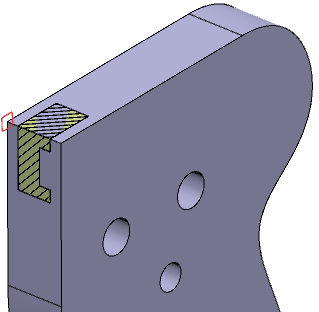
In the tree, the Restricted Area.x node is created and the
restricted area appears with hatching lines on it.
Important:
The pattern representation for the restricted area is displayed for
planar surfaces only.
When a restricted area is not valid, in the tree, a yellow filled circle is displayed on the icon. Right-click the
restricted area in the tree and select Diagnostic Report.
When the restricting elements are not included in the restricted
elements, a warning message is displayed.
You can edit a restricted area:
In the tree, double-click the RestrictedArea.x
node.
In the Restricted area dialog box,
you can only select the Connection
Management icons or
OK or
Cancel.
Modifications made with the Connection
Management cannot be undone.
Optional:
To change the representation of the restricted area, right-click the
Restricted Area.x node, select
Properties, and then the
Pattern tab.
Alternatively, right-click the restricted area to access its
properties.
From the Type list, you can select
Dotting, Coloring,
Image, or None and specify the
required attributes.
Notes:
You can also right-click in the 3D area, select Display > Object Properties, and then change the representation pattern for the
restricted area.
You can filter the restricted area by applying 3D annotation filter.
For more information, see Filtering Annotations.
In the 3D area, the restricted area is displayed even though the corresponding
reference geometry is hidden.
The restricted area is represented with the selected pattern
type.
To generate a drawing representing the restricted area which is in show mode
with at least one annotation and restricted surface, follow the below
steps:
From the Compass, click Drafting.
From the View Layout section of the action bar, click View from 3D and then select the required view to generate
its drawing.
Notes:
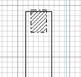
When you generate a drawing for the view parallel the restricted
area, the restricted area is displayed in the drawing with the
selected pattern on it.
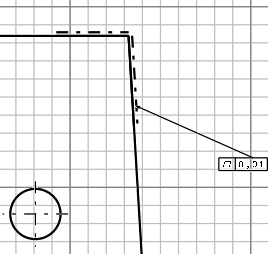
When you generate a drawing for the view orthogonal to the
restricted area, the offset dotted line represents the restricted area.
2D Drawing: View Parallel to the Restricted
Area
2D Drawing: View Orthogonal to the
Restricted Area
The offset dotted lines representing the restricted area can be
towards the material region, the case of Generative Shape Design surfaces, for example.
The restricted area is represented in the drawing generated using views
and its boundary is marked with dotted lines.
 .
.
 becomes available. For more information, see Connections Management for Annotations.
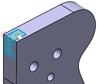
 and then select the required view to generate
its drawing.
and then select the required view to generate
its drawing.