Creating Semantic Geometrical Tolerance | |||
| |||
-
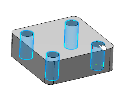
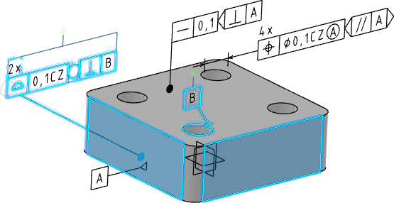
Select multiple holes as shown below.
-
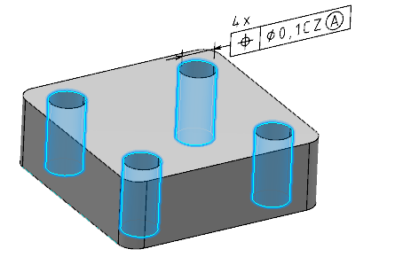
In the
General tab, select the
Display CZ modifier check box and keep the
remaining options as they are.
You can click Display median feature symbol to display the median feature symbol in the tolerance frame.
-
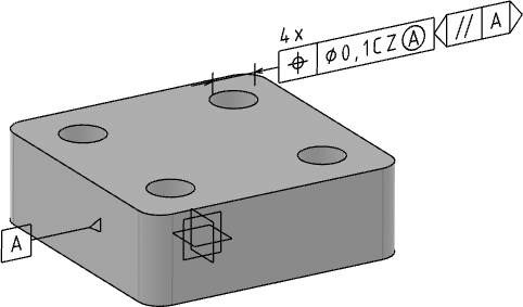
Under
Two Parallel Planes Tolerance Zone, specify
the geometrical tolerance symbols for orientation plane auxiliary plane
indicator. To do so:
-
From the list, select the required auxiliary feature
indicator.
When you select angularity
 , a theoretically exact dimension is created between the
constructed geometry and the datum feature.
, a theoretically exact dimension is created between the
constructed geometry and the datum feature.
-
Specify the required datum feature.
If not available, from the list, you can select Create datum and create it. This datum feature is not removed even when you delete the specified geometrical tolerances.
The auxiliary plane indicator, Orientation plane, Intersection plane, or Collection plane, appear automatically based on the selected elements.
-
From the list, select the required auxiliary feature
indicator.
- Optional:
To specify the geometrical tolerance indicators for intersection
plane auxiliary plane indicator:
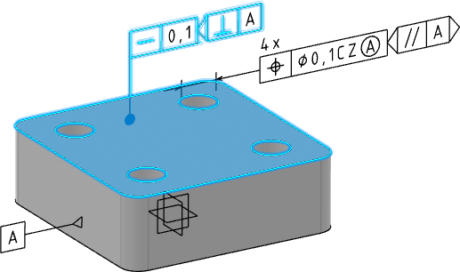
-
Select the face of the feature as displayed and then the
Straightness Specification
 .
.
-
In the
General tab, under
Toleranced Lines Definition, specify the
geometrical tolerance indicators for intersection plane. To do so:
- From the list, select the required auxiliary feature indicator.
- Specify the required datum feature.
Note: The leader extremities of geometrical tolerance are always a filled circle except when there are extension lines or when they are
in the alignment of dimensions.
except when there are extension lines or when they are
in the alignment of dimensions.
-
Select the face of the feature as displayed and then the
Straightness Specification
- Optional:
To specify the profile of a line or a surface geometrical
tolerance indicators applied in common zone to several features for collection
plane auxiliary plane indicator:
- Select multiple faces and then the Profile-of-Surface specification.
-
In the
Toleranced Feature tab, under
All round, specify the geometrical
tolerance indicators for collection plane. To do so:
- From the list, select the required auxiliary feature indicator.
- Specify the required datum feature.
Note: All the auxiliary feature indicators become invalid when you switch to ASME standard. -
In the
Tolerance Zone tab,
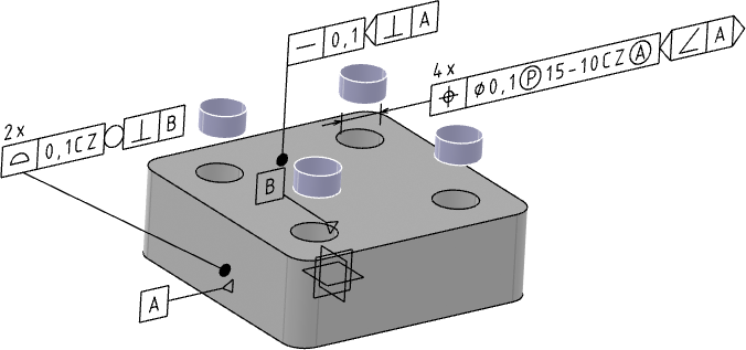
- Click Projected Tolerance Zone.
-
Click
Create/Edit available next to the
Extended Cylinder Selection list.
The Extended Cylinder Construction Geometry dialog box appears.
- In the Reference plane box, select the reference face on which the hole is created.
- In the Length and Offset boxes, enter the required length and offset of the extended cylinder from the reference plane respectively.
- Click OK.
-
In the
Geometrical Tolerance dialog box, select the
Show length and offset in tolerance frame
check box.
The length and offset values are displayed in the tolerance frame.
-
Click
OK.
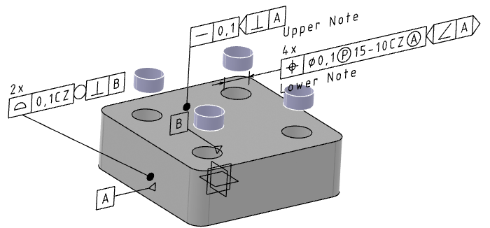
The geometrical tolerance feature is created on the selected holes.
-
For the selected semantic geometrical tolerance, datum target
annotation, and the datum systems, to modify the numerical display properties
specified under
Geometrical Tolerance and Datum Target,
available in
Me
 > Preferences > App Preferences > 3D Modeling > Mechanical Systems
expander:
> Preferences > App Preferences > 3D Modeling > Mechanical Systems
expander:
- Right-click the datum target annotation and select Properties.
- In the Properties dialog box, click the Numerical Display tab.
- Under Numerical Display and Format, modify the required options.
For more information about numerical display properties defined in , see Geometrical Tolerance, Datum Target, and Datum System.
The datum target annotations are displayed according to the modified display properties.