You can create a section cut view/annotation
plane.
Important:
Clicking anywhere in
3D area
is equivalent to click
OK in the dialog
box associated with this command.
Before you begin: Open an existing 3D shape.
From the
View Layout section of the
action bar
,
click
View From
Reference.
The
Tools Palette
appears.
Select Section Cut from the
Tools Palette.
Important:
Only selection of planar element is compatible/authorized with this
command. You must select a planar element to complete the operation.
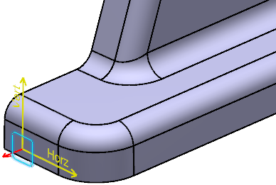
Select the face as shown.
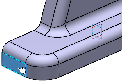
The View Creation dialog box appears.
In the Ratio Assistant panel, specify the view ratio.
Annotation set ratio: to set the view ratio same
as it is specified for annotation set. The value can be in fraction or
decimals.
By default, this option is selected.
Current zoom level: to set the ratio according to
the current zoom level. The value is in decimals.
Suggested ratio: to set the suggested ratio
proposed in the list of predefined values based on the current zoom
level.
To customize the list of predefines values, see Ratio Assistant.
Tip:
Select
the Propagate to annotation set check box to
propagate the specified ratio to the annotation set. When this check box
is selected, the specified view ratio is persisted when you open the
Ratio Assistant panel.
Click OK in the View creation
dialog box.
The section cut view is created. Section views are represented by a
yellow reference axis and are identified as Section Cut
View.x in the tree.
Tip:
When you select an empty view/plane annotation, its normal axis is red colored until you create an annotation.
To change the view ratio, select the view in the 3D area and, on the context toolbar, select Change Ratio.
You can also right-click the view in the Views and Captures panel and select xxx object > Change Ratio.
Optional: Right-click the required view to use the clipping commands.
Option
Description
Clipping > Clip View
Lets you select or create a sketch profile to clip the view.
Clipping > Replace Clipping
Lets you select or create a sketch profile to replace the existing clipping profile.
Clipping > Unclip View
Lets you unclip the view.
Note:
You can select several clipped views to unclip.
When you right-click the clipped view and select Display View, the complete view is displayed instead of the clipped view, and only the clipping sketch profile is displayed.