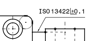
Annotating the Edges of Undefined Shapes | ||
| ||
-
From the Annotation section of the action bar,
click the Edge of Undefined Shape Symbol
 .
.
-
Select one or two elements defining the edge, to determine the position of the leader's
anchor point.

-
Move the pointer and position the symbol, or snap the leader orientation on one of the
privileged directions and position the symbol.
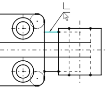
The leader segment turns to cyan color
 ,
indicating the snapping on the privileged direction. Note: If the leader is associated with two line references, it can be snapped on the horizontal and vertical directions, and also on the angle bisector line direction between the two line references. In this case, a positional link is created between the leader and the two line references.
 -
In the Edge of Undefined Shape Symbol dialog box, specify values
in the required zone boxes.

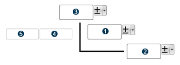
Zone Numbers Significance 
Lets you specify the type of undefined edge. - +: for permitted excess material (passing).
- -: for excess material removal (undercut).Notes:
- You can add the symbols (+ and -) using the keyboard.
- Press Shift + Enter to add a new line.
 and
and 
Let you define the direction of passing or undercut. - Unidirectional direction: The indication of one direction of passing on an external edge or undercut on an internal edge.
- Asymmetrical indication: The indication of directions of undercut on an external edge or passing on an internal edge.

Lets you specify the limited area where an edge of undefined shape is valid. 
Lets you add the individual indication of edges. You can specify the indication of edges for the following features:
- Edges vertical to the projection plane.
- Edges of a feature, such as a hole.
- Edges of the front and the back, specifying the quantity of edges.
- All edges around the profile of a represented part.

Lets you specify a single indication for all the edges of an object. Note: The values entered for the zones are saved for the next usage.
- Right-click the edge of an undefined shape symbol and select Properties.
-
In the Text tab, specify an anchor mode between the following:
- Global: The whole bounding box of the edge of undefined shape symbol is taken into account for its positioning.
- Symbol: An edge of undefined shape symbol can be positioned on the geometry corner.
- From the Anchor Point list, select the position of the anchor point to specify the position of the annotation.
- Optional:
To customize the edge of undefined shape symbol, click Me > Preferences > Standards and modify the standards.
For more information, see Edge of Undefined Shape.