Reconstructing the Concept Shape | |||
| |||
-
From the Shape Reconstruction section of the action bar, click Milling
Reconstruction
 .
.
You can also double-click the icon to repeat the command and obtain the reconstruction in all directions.
The design space is automatically retrieved if there is one. You can right-click Clear Selection to remove it and perform the reconstruction without considering the design space geometry. - Select the concept shape.
-
Select a geometric element as the milling direction.
You can click
 to reverse the orientation of the
milling direction or
 to select the
milling direction from the viewpoint. You can also press
F4 to select the camera's viewpoint.
-
To create symmetrical elements, select the available symmetry controls.
It is only available provided that the Compute Shape command was performed using a symmetry constraint.
-
Click
Preview.
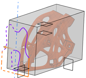
Inner profiles of the original side are previewed with full lines whereas inner profiles of the other side are previewed with dotted lines. You can click the handles to reverse the symmetrical side.

Colors of the silhouette are the following:
Color Description Violet Default color Orange Sections of the profile belonging to the design space (if defined) Green Profiles with a dimension type (pockets) Pink Approximation of the profile -
Optional: Select limit faces.
A limit face can be a plane or a planar surface, which normal is perpendicular to the milling direction. It must completely intersect the shape.
Silhouettes are previewed in different planes to visualize the groups of profiles concerned by each limit.Note: You can remove a limit face by selecting it again or using the context menu. - Define the tool diameter.
- Click Next.
-
Define the approximation type and strategy for each profile.
Levels of accuracy for each profile depend on the chosen approximation strategy:
- If you select Custom as the polygonal strategy, you can define a tolerance. By default, the tolerance value corresponds to the medium tolerance.
- If you select Spline, you can create more accurate profiles as it generates a sketch containing lines, circles, and splines.
- If no strategy is applied, it means that it is a design space with a frozen region.
The first selected profile imposes its strategy to the following selected profiles. To select several profiles in the list, press Shift + Ctrl. To select profiles on the shape, press Ctrl and click a profile. If you define a different strategy, it applies to all the selected profiles.
The silhouette of the concept shape based on the tool diameter is computed using the milling direction and the opposite direction to detect non-through pockets, that is pockets with a dimension. - In Profile definition, select or clear the profiles to keep creating the pocket.
-
From the
Strategy list, define the level of accuracy.
Levels of accuracy for each profile depend on the chosen strategy law. If no law is applied, it means that it is a design space with a frozen region.
Selecting Spline lets you create more accurate profiles as it generates a sketch containing lines, circles, and splines.
- Optional:
Define a threshold width.
Its value is the same as the tool diameter, it can only be increased. Increasing the value prevents certain profiles to be milled.
-
Define the milling depth.
By default, its value is slightly superior to the maximum height computed among the profiles. Decreasing the value clears incompatible profiles.
- To visualize the milling of the concept shape, click Preview.
-
Click
OK.
In the tree, pockets and iso-constrained sketches are created under the Milling_Block node and can be edited.