Visualizing the Overhang Analysis | ||
| ||
-
From the View section of the action bar, click View
Modes
 , and
click Shading with materials
, and
click Shading with materials
 .
.
-
From the Shape Review section of the action bar, click ALM Overhang Analysis
 .
.
-
Define the printing direction:
Option Description  User
UserLets you position and manipulate the Robot on the structure. You can click Reverse direction  to
reverse the direction of the Robot.
to
reverse the direction of the Robot. Feature
Lets you select a feature as the direction. - The yellow color shows the threshold angle that requires the use of supports.
- The green color shows the surfaces that are contained within the tolerance area.
- The red color shows the surfaces that are perpendicular to the printing direction.
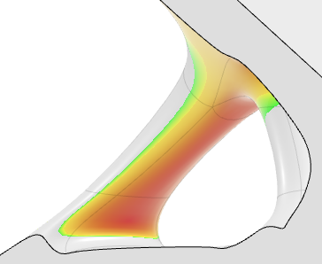
Tip: You can modify the color code by clicking any color square. -
Click Compute.
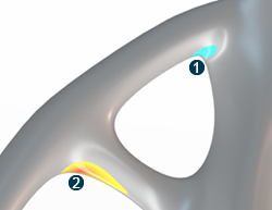
 : zones that
have a width smaller than the minimum width are shown in the color
corresponding to the small overhang regions.
: zones that
have a width smaller than the minimum width are shown in the color
corresponding to the small overhang regions. : zones that
have a width greater than the minimum width are shown in the color
corresponding to the large overhang regions.Note: This filter mode is not persistent.
: zones that
have a width greater than the minimum width are shown in the color
corresponding to the large overhang regions.Note: This filter mode is not persistent.