-
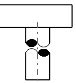
Double-click a S break symbol.
-
In the S Break Edition dialog box, select the
Hollow check box to make the symbol hollow.
- Optional:
To remove the filling inside the symbol, clear the Filled check
box.
-
To change the ratio of the symbol size, drag the slider.
-
To reverse the direction, click Reverse.
-
Click the required boxes and select a color, line type, and line thickness from the
list.
You can define the S break symbol parameters from the generative
view styles (GVS). For more information, see S Break Edges.
Notes:
- While creating new S break symbols, the overridden GVS values are considered. In the
case of the existing S break symbols, the overridden GVS values are not reflected on the
symbols.
- The cylindrical geometry must be fully cut through its diameter.
- The cylindrical geometry must be fully visualized in a view whose projection plane is
parallel to the axis cylinder.
- The existing S break symbols are updated.
- If a S break symbol becomes invalid due to the modifications in the 3D part, it is
automatically removed after updating the view.
- If you delete the S break symbol, this symbol can be restored only by using the
Restore Properties command.