Positioning a View

You can position a generative or an interactive view by aligning, superposing or setting relative view position of a view.

This task shows you how to:


Before you begin: Open or create a drawing representation.

Align Views Using Elements

You can align (translate) a view with another view using geometrical elements (projected as lines, circles, or points).

  1. Right-click the view that you want to reposition and select View Positioning > Align Views Using Elements.
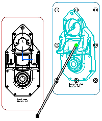
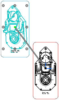
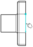
  2. On this view, select the first geometrical element that you want to align.

    This element may be projected either as a point, a line or a circle (aligned according to its center). A visual feedback is provided to indicate the kind of geometry detected, and in the case of a line, its orientation (the orientation being determined by the proximity of the pointer with one of its extremities).


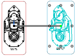
  3. On the reference view, select the geometrical element that you want to align.


    Notes:
    • If both the selections are lines, you can press Shift before clicking the second element to view where both the line origins meet. In this case, both the lines will be made collinear and their origin points coincident.
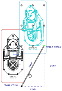
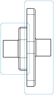
    • If the lines are parallel, both the views are aligned.
    • If the lines are non-parallel, the first view is oriented according to the reference element selected, without any alignment.

    The first view is moved, and both views are aligned according to the elements and orientations you selected. Any associative positional link that existed between the two views prior to their alignment is removed, and no new one is created.


    Tip: If you want to restore an associative positional link between the views, you can right-click the view and select View Positioning > Position According to Reference View.

Superpose Views

You can superpose a view with another view according to their origins.

  1. Right-click the view that you want to superpose, and select View Positioning > Superpose.
  2. Click the view on which you want to superpose the first view.
    The first view is moved and superposed on to the second one.

  3. Click in the drawing, outside the views, to validate the superposition.

Set Relative View Position

You can reposition a view relatively to various elements (a line/callout, a point or the frame of a view).

  1. Right-click the view frame that you want to reposition and select View Positioning > Set Relative Position.
    A direction positioning line appears that is related to the isometric view. You can now position this isometric view as desired relatively to the front view using the anchor points assigned with it.


  2. Select the black square point of the direction positioning line end.

    Once you click the end square point, it becomes a blinking red end point and remains so until you select a point or a view frame.

    You can also click the direction positioning line. In this case, the positioning line becomes a blinking line and remains so until you select a line (callout line).


    Tip: Press Ctrl to move the positioning line according to a direction that is parallel to the positioning line.
  3. Click the edge according to which you want the isometric view to be aligned.
  4. Click one anchor point. For example, the lower-right anchor point.
    The view anchor point is aligned according to the green point and thereby to the direction positioning line. As you move the pointer over the direction positioning line, the position and length coordinates of the line appear.


    Note: You can also select the front view frame and align the isometric view to the front view according to the barycenter.

  5. Optional: Rotate the isometric view using the green point.
  6. Translate the isometric view along the direction line and locate it at the desired distance using the direction positioning line.


    Important: If you modify the length of the direction positioning line, this new length will be kept for the positioning modifications you will be applying to the isometric view. Note that if you had previously positioned this isometric view according to a point, then, not only the line length but also the line angle will be kept.
  7. Click in the free space to validate and leave the relative positioning mode.

Important:
  • In relative positioning, if you try to move the view outside of the anchor point frame, the relative positioning mode will be lost.
  • However, you can align a view relatively to one of the edges that are within this view. To do this, first select the direction positioning line, and then select an edge on the view to be aligned. As a result, the handles automatically align according to this selected edge.