About Dimensioning Tools | ||||
|
| |||
Dimensioning Tools in the Tools Palette
![]()
The Tools palette appears whenever you select a command for which specific options or value boxes are available. This enables you to know immediately when specific tools are available for a command. The options or boxes available in the Tools Palette depend on the command you selected, and on the context.
When selecting Dimensions, the Tools Palette provides a number of options which are described in the table below.
| Icon | Command | Description |
|---|---|---|
|
|
Projected Dimension (according to the cursor position) |
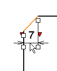 |
|
| Force Dimension on Element |
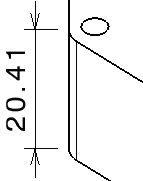 |
|
| Force Horizontal Dimension in View |
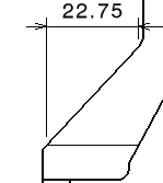 |
|
| Force Vertical Dimension in View |
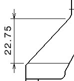 |
|
| Force Dimension along a direction |
 |
|
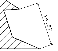
| True Length Dimensions (for isometric views only) |
 |
|
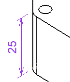
| Intersection Point Detection |
Dimension Properties
The Dimension Properties in the Object Properties panel lets you apply the given properties to all the dimensions you are going to create.
The following properties are available:
- Line type (regular, two parts, one part leader, or two
parts leader)Note: When you select the Two Parts or Two Parts Leader options for the Line type, the dimension line representation is set to two parts or two parts leader, and its second part is oriented horizontally according to the screen.
- Tolerance type
- Tolerance value
Important:
|
Numerical Properties
The Numerical Properties in the Object Properties panel lets you apply numerical properties to all the dimensions you are going to create.
The following properties are available:
- Numerical Display Format
Important: When creating a new drawing, the Numerical Display Format box (here: NUM.DIMM) drives the unit of the dimensions to be created. By default, the value used in this box for each type of dimension is defined by the dimension styles ( > [standard name] > Styles > [dimension style] > ValueDisplayFormat > MainValue > Name). However, if no value is defined by the styles, the default value is the one defined in section. - Precision
Precision values are interpreted in either of the following formats:
- Decimal format: Values lower than or equal to one are interpreted using the decimal format.
By default , the following decimal values are proposed:
1.0 - 0.1 - 0.01 - 0.001 - 0.0001
- Fractional format: Values greater than one are interpreted using the fractional format.
For example, 10 is interpreted as 1/10.
By default, the following fractional values are proposed:
10 - 100 - 1000 - 10000
- Decimal format: Values lower than or equal to one are interpreted using the decimal format.
Style
You can use styles (i.e. a set of default values for each kind of element) when creating dimensions. Styles are defined in the standard used by the drawing and managed by the administrator.
When creating a dimension, the Style in the Object Properties panel displays the styles available for this type of dimension. If only one style is available, it will be used by default.
If several styles are available for this type of dimension, you can choose the style that you want to use to create this dimension by selecting it from the Style.