About Creating Arrows | ||||
|
| |||
General Information
This sub-topic provides general information about arrows.
- Arrow angle and length are defined by standards. For more information, see Dimension Parameters.
- The arrow and the selected object are associative.
Arrow Modification
This sub-topic provides more information about arrow modification.
- You can modify the general appearance of an arrow, by either clicking the arrow and using the Graphic Properties in the Object Properties panel, or right-clicking the arrow and using the Graphic tab in the Properties dialog box.
- You can scale the arrow extremities according to the scale of the view.
In the Standards Definition dialog box, select the Styles node. In the Arrow > Apply Scale On Extremities select Yes to scale the arrow extremities.
Tip: You can also select the Apply scale on extremities check box from the arrow properties. - You cannot add another extremity to an arrow.
- To modify the position of an arrow, click it and use the handles to drag it to its new location.
Arrow Orientation
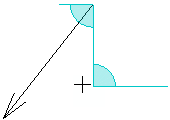
When creating an arrow, you can orient it by snapping its orientation on the following privileged directions:
- Horizontal and vertical directions:
- Computed in the sheet for annotations oriented in the sheet.
- Computed in the view for annotations oriented in the view.
- Reference normal and tangent directions:
- The reference can be a geometry or an annotation.
When creating an arrow, the arrow head is considered as a fix point, however, you can move the arrow segment so that the arrow segment is snapped on the privileged direction. When the arrow segment is snapped on any of the privileged directions, it turns blue.

The following points are considered when snapping a leader extremity on its privileged directions:
- The selection of a geometry or an annotation: If an annotation providing attachment points is selected as a reference, the annotation position is snapped on the selected attachment point and its leader is removed.
- The snapping on the paper grid: If Snap by default (SHIFT toggles) check box is selected in expander, under Paper Grid, and no reference is selected, the position is first snapped on the privileged direction and then on the closest grid point or grid line (if no grid point is located on the privileged direction).
| Important: If Text check box is selected in expander, under Create leader extremity normal to reference (Ctrl toggles), the text leader is oriented perpendicularly to the reference, by default. In this case, the snapping on privileged directions is no more available when selecting a reference. Though in this case, the orientation link is created, because Snap on privileged directions check box is selected. |
- Snapping Using Shift
- If you press Shift when an arrow is snapped on a privileged direction, the arrow stays snapped on this privileged direction whatever the position of the mouse pointer is till you release Shift.
- If you press Shift when a multipoint arrow is snapped on different directions, the arrow or the breakpoint (under manipulation) cannot be moved anymore.

In this case, Shift no more toggles the snapping on the paper grid.
- If the Snap by default (SHIFT toggles) check box is selected, the position is snapped on the privileged direction and then on the closest grid point or grid line.
- If the Snap by default (SHIFT toggles) check box is cleared, the position is snapped only on the privileged direction.